
Circuit Theory/All Chapters
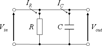
The schematic of an electric circuit typically illustrates the arrangement of components and their interconnections, providing a visual representation of the circuit's functionality. In a basic AC or DC circuit, essential elements such as resistors, capacitors, and inductors are represented using standardized symbols. For example, a resistor is depicted as a zigzag line, while a capacitor is shown as two parallel lines. The connections between these components are indicated by lines that represent conductive paths.
In the context of circuit theory, Kirchhoff's laws play a crucial role in analyzing circuit behavior. Kirchhoff's Current Law (KCL) states that the total current entering a junction equals the total current leaving the junction, while Kirchhoff's Voltage Law (KVL) asserts that the sum of the electrical potential differences around any closed network is zero. These laws are fundamental for setting up equations that describe circuit behavior, allowing for the calculation of unknown values such as current and voltage across various components.
The use of phasors in AC circuit analysis simplifies the calculations involving sinusoidal signals. Phasors represent sinusoidal waveforms as complex numbers, making it easier to perform algebraic operations on them. The conversion between the time domain and the phasor domain is facilitated through Euler's formula, which links exponential functions to trigonometric functions.
In addition to basic components, more complex circuits may include operational amplifiers, diodes, and transistors, which introduce non-linear behaviors and require more advanced analysis techniques. The schematic for such circuits would include the corresponding symbols for these components, along with their connections, to provide a comprehensive view of the circuit's operation.
Overall, the understanding of electric circuits is foundational for electrical engineering, and this text aims to equip students with the necessary knowledge and tools to analyze and design various types of circuits effectively. The progression from basic concepts to more complex applications, including digital signal processing, reflects the evolving nature of the field and the importance of a solid theoretical background in practical engineering tasks.This wikibook is going to be an introductory text about electric circuits. It will cover some the basics of electric circuit theory, circuit analysis, and will touch on circuit design. This book will serve as a companion reference for a 1st year of an Electrical Engineering undergraduate curriculum.
Topics covered include AC and DC circuits, passi ve circuit components, phasors, and RLC circuits. The focus is on students of an electrical engineering undergraduate program. Hobbyists would benefit more from reading Electronics instead. The main editable text of this book is located at. The wikibooks version of this text is considered the most up-to-date version, and is the best place to edit this book and contribute to it. The theory of electrical circuits can be a complex area of study. The chapters in this section will introduce the reader to the world of electric circuits, introduce some of the basic terminology, and provide the first introduction to passive circuit elements.
This is designed for a first course in Circuit Analysis which is usually accompanied by a set of labs. It is assumed that students are in a Differential Equations class at the same time. Phasors are used to avoid the Laplace transform of driving functions while maintaining a complex impedance transform of the physical circuit that is identical in both.
1st and 2nd order differential equations can be solved using phasors and calculus if the driving functions are sinusoidal. The sinusoidal is then replaced by the more simple step function and then the convolution integral is used to find an analytical solution to any driving function.
This leaves time for a more intuitive understanding of poles, zeros, transfer functions, and Bode plot interpretation. For those that have already had differential equations, the Laplace transform equivalent will be presented as an alternative while focusing on phasors and calculus.
This book will cover linear circuits, and linear circuit elements. The goal is to emphasize Kirchhoff and symbolic algebra systems such as matLab mupad or mathematica at the expense of node, mesh, Norton, etc. A phasor/calculus based approach starts at the very beginning and ends with the convolution integral to handle all the various types of forcing functions.
The goal is set the ground work for a transition to the digital version of these concepts from a firm basis in the physical world. The next course would be one focused on modeling linear systems and analyzing them digitally in preparation for a digital signal ( DSP ) processing course.
For a technician version of this course which focuses on the real rather than the idea, expertise rather than theory, on algebra rather than calculus, see the Electronics wikibook There are a few key terms that need to be understood at the beginning of this book, before we can continue. This is only a partial list of all terms that will be used throughout this book, but these key words are important to know before we begin the main narrative of this text.
The time domain is described by graphs of power, voltage and current that depend upon time. The "Time domain" is simply another way of saying that our circuits change with time, and that the major variable used to describe the system is time. Another name is "Temporal". The frequency domain are graphs of power, voltage and/or current that depend upon frequency such as Bode plots.
Variable frequencies in wireless communication can represent changing channels or data on a channel. Another name is the " Fourier domain ". Other domains that an engineer might encounter are the "Laplace domain" (or the "s domain" or "complex frequency domain"), and the "Z domain". When combined with the time, it is called a "Spectral" or " Waterfall. " Circuits generally have inputs and outputs. In fact, it is safe to say that a circuit isn`t useful if it doesn`t have one or the other (usually both).
Circuit response 🔗 External reference
Related Circuits
A remote control light switch designed to fit into an existing light switch panel requires a 3.3V DC power supply for its electronics. However, the panel contains only two wires: one live wire and one wire that connects to...
With a 1.5V battery supply, the integrated circuit LM3909 can drive the light-emitting diode NSL5027. The 300μF electrolytic capacitor acts as a timing capacitor, which limits the flash speed to approximately 1Hz. The circuit utilizes the LM3909, a popular LED...
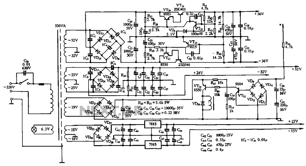
The power supply circuits for servo systems are critical during both the adoption and operational stages. The power supply circuit for servo systems is designed to provide stable and adequate voltage and current levels necessary for the servo motors to...
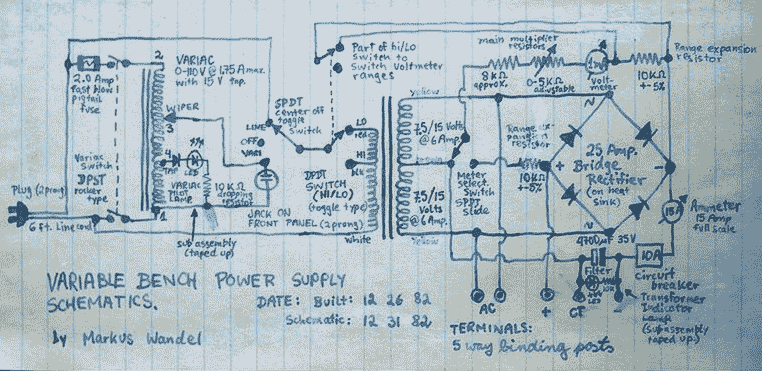
This power supply is able to deliver adjustable center-tapped DC from 0 to about 30 volts, as well as AC directly from the Variac and from the main transformer before the rectifier. What's primitive by today's standard is that...
This sound-activated switch allows for sound control, which can be beneficial not only for robotic applications but also for home automation. The sound-activated switch operates by detecting specific sound frequencies or patterns, enabling the user to control various devices or...
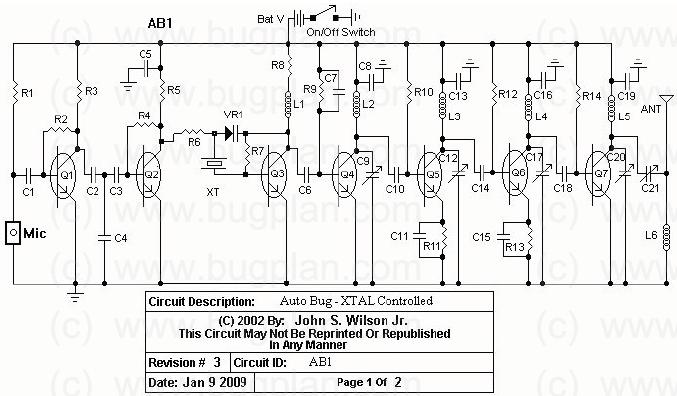
This circuit operates between 150 to 165 MHz. The crystals used are Digi-Key Electronics Barrel Crystals of the CA-301 type, which are relatively inexpensive. Any fundamental crystal with a frequency between 14 and 17 MHz can produce an output...
Warning: include(partials/cookie-banner.php): Failed to open stream: Permission denied in /var/www/html/nextgr/view-circuit.php on line 713
Warning: include(): Failed opening 'partials/cookie-banner.php' for inclusion (include_path='.:/usr/share/php') in /var/www/html/nextgr/view-circuit.php on line 713