
Bench Power Supply circuit
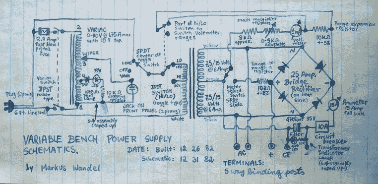
The described power supply circuit is a versatile device capable of delivering both adjustable DC and AC voltages, making it suitable for various applications, particularly in experimental setups and for powering low-power electronics. The core components of the system include a Variac, which functions as a variable autotransformer, allowing for the adjustment of AC voltage output. The main transformer serves as a step-down transformer to convert the high voltage AC mains to a lower voltage suitable for the application.
The power supply features a center-tapped configuration, enabling the generation of a dual-polarity DC output. This output can be adjusted from 0 to approximately 30 volts, providing flexibility for different load requirements. It is important to note that the power supply lacks voltage regulation, meaning that the output voltage can fluctuate significantly based on the load connected. For instance, if the output is set to 12 volts under a heavy load and the load is subsequently removed, the voltage will increase due to the absence of current draw. This characteristic is acceptable for applications involving motors and low-power devices, where precise voltage regulation is not critical.
The construction of the power supply involved the integration of various components, including electrolytic capacitors, binding posts, and a bridge rectifier, which were sourced from commercial outlets like Radio Shack. The bridge rectifier is essential for converting the AC output from the Variac and transformer into a usable DC voltage. The design also includes a voltmeter for monitoring the output voltage, although the original scale was replaced due to wear over time.
The project reflects a hands-on approach to electronics, with an emphasis on repurposing and modifying existing components. The experience of rewinding transformers highlights the resourcefulness involved in building such a power supply, demonstrating a practical understanding of electromagnetic principles and circuit design. Overall, this power supply serves as a testament to the ingenuity and creativity often found in the field of electronics engineering.This power supply is able to deliver adjustable center-tapped DC from 0 to about 30 volts, as well as AC directly from the Variac and from the main transformer before the rectifier. What's primitive by today's standard is that it is not voltage regulated; i.e. if you adjust it to 12V for a heavy load, and then disconnect the load, the voltage will go up quite a bit.
But for motors and very low power electronics it didn't matter. I had to buy the electrolytic capacitors, binding posts and bridge rectifier at Radio Shack. Pretty much everything else was scrounged from somewhere. The voltmeter originally had a hand-drawn paper scale inserted into it, but over the years it warped and blocked the meter needle so I just removed it. Nowadays I have better voltmeters anyway. Back before we had computers to occupy all our time, my brother and I were always tinkering with motors and electronic junk and such. This required electrical power, and good power supplies were hard to come by, so we each ended up building our own.
We had few parts and lots of time, so we each ended up taking apart and rewinding transformers at one time or another - I rewound the primary of a 220V transformer (from Germany) for 110V, Matthias rewound, I think, both windings of a transformer to convert it to 110V and put many taps in the secondary for various voltages. This project got started when I was given a defective Variac (a variable autotransformer - the shiny copper coloured thing at the bottom right of the inside front panel) and an old rusty car battery charger with a big beefy 6 ampere transformer inside.
I was able to fix the Variac by reconnecting the break in the winding. 🔗 External reference
Related Circuits
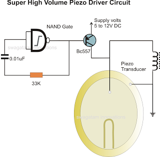
In the previous post, a piezo transducer element was discussed, along with its application in electronic circuits. This article will explore how a piezo transducer can be driven or operated using a simple circuit. The amplification method differs from...
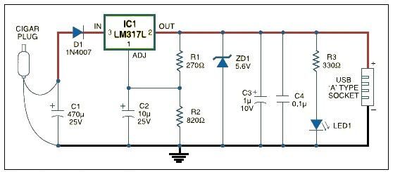
USB car charger adapter circuit design using LM317 regulator circuit The USB car charger adapter circuit utilizing the LM317 voltage regulator is designed to convert a car's 12V DC power supply into a stable 5V output, suitable for charging USB-powered...
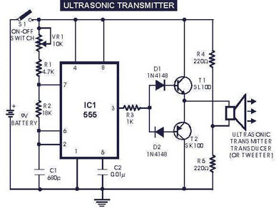
The circuit generates and transmits ultrasonic sound at frequencies between 40 and 50 kHz. It consists of a mini transmitter and a receiver circuit, where the transmitter produces ultrasonic sound, and the receiver detects this sound to activate a...

The duty cycle of the capacitive circuit is very low, ranging from 1% to 10%. When the current is only 50 mA, the battery current consumption is just 1 A. Resistor R4 and capacitor C control the opening time,...
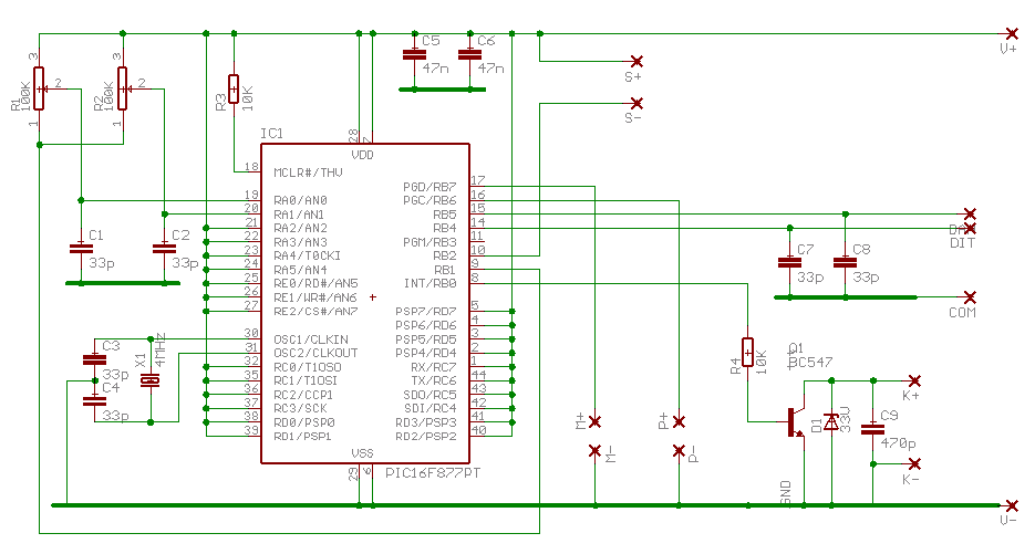
A larger version of the circuit diagram can be accessed by clicking here. The circuit was created using Eagle from CadSoft, which is a free schematic and PCB layout software for small non-commercial projects. The core component of the...
This Korean SuperCap OEM supports usage in series configurations. Consider whether the implementation will be manual or automatic, such as with a smart battery charger or a power fail backup circuit. It is essential to balance the voltage and...