
Power amplifier circuit diamond differential input
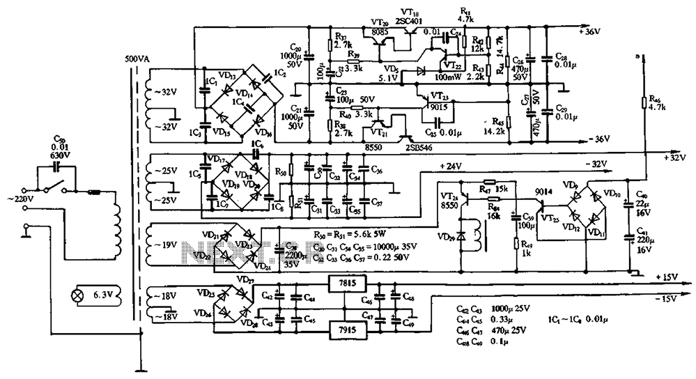
The power supply circuit for servo systems is designed to provide stable and adequate voltage and current levels necessary for the servo motors to function effectively. During the adoption stage, the circuit must ensure that the servos receive the correct power to facilitate initial testing and integration into the system. This involves using voltage regulators to maintain a constant output voltage despite variations in input voltage or load conditions.
In operational stages, the power supply must be capable of handling dynamic loads as servo motors often experience rapid changes in current demand during operation. This can be achieved through the use of capacitors for smoothing out voltage fluctuations and inductors to filter out noise. Additionally, protection circuits such as fuses or circuit breakers should be implemented to prevent damage from overcurrent situations.
Furthermore, it is essential to consider the power supply's efficiency, as excessive power loss can lead to overheating and reduced performance. Utilizing switching regulators instead of linear regulators can enhance efficiency, especially in battery-operated applications where power conservation is critical.
In summary, the design and implementation of the power supply circuits for servo systems are essential for ensuring reliable performance throughout both the adoption and operational stages, requiring careful consideration of voltage regulation, load handling, and overall efficiency. Before and after the adoption stage and servo circuits are power supply.
Related Circuits
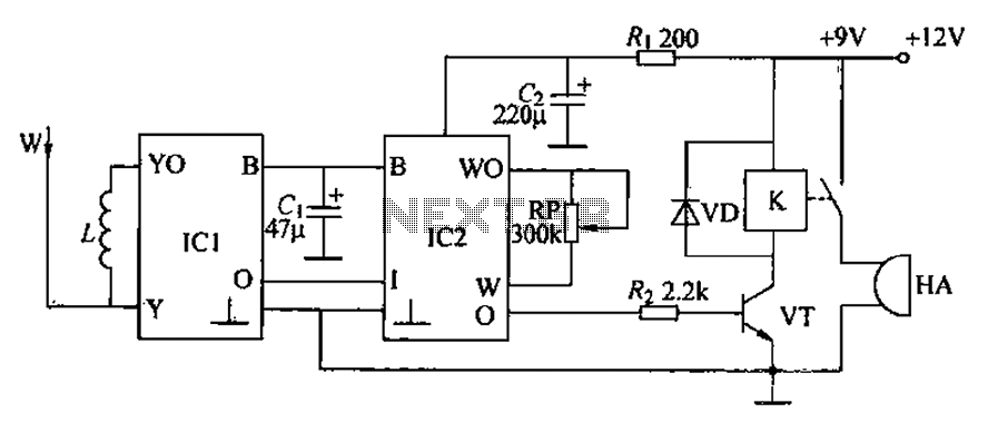
A circuit for an inductive burglar alarm is derived from a radio scanning detection circuit, which includes a signal processing circuit and an alarm circuit. The radar detection circuit module consists of components such as microwave emission, low-pass filtering,...
The circuit for the solar-powered controller includes a switching circuit, a pulsing circuit, and a high-voltage output circuit. The external power components consist of a 1- to 5-W solar panel and a 12-V motorcycle or camcorder battery. The output...
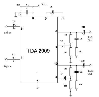
The circuit features a Class AB audio amplifier integrated circuit (IC) that necessitates only a minimal number of external components. This series is straightforward to construct. The 10W stereo amplifier circuit requires a stable power supply with a voltage...
A DIY GSM jammer schematic diagram designed for use with GSM1900, operating within the frequency range of 1930 MHz to 1990 MHz. The GSM jammer circuit is intended to disrupt communication between mobile phones and base stations within the specified...
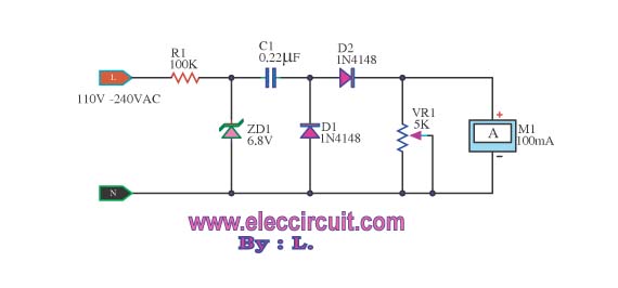
This meter displays the frequency of a power generator, which operates at a voltage range of 110V-240V and a frequency range of 10-100Hz. The output sine waves are converted to square waves. The described frequency meter is designed to accurately...
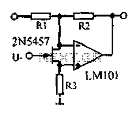
A 1.53 voltage-controlled gain amplifier (VGA) utilizes a FET connected between the two inputs of the operational amplifier (op-amp) as a voltage-controlled resistance. The resistance changes linearly with voltage and varies from several dozen square ohms, exhibiting excellent control...