
Circuit to Measure Power Supply Voltages
The described circuit is a power management and monitoring system designed for a weather station application. It utilizes a linear voltage regulator to supply a stable 3.3 V to the microcontroller, ensuring that the analog-to-digital conversion process is accurate and reliable. The voltage divider, composed of two 10 kΩ resistors, serves to scale down the voltage from the solar panel to a safe level for the microcontroller's ADC. This design choice is critical, as it allows for the measurement of both the solar panel and battery voltages without exceeding the microcontroller's maximum input voltage specifications.
In scenarios where the system may be disconnected, the design thoughtfully considers potential issues with backfeeding voltage through measurement points TP1 and TP2. The resistive nature of R1 and R2 acts as a safeguard, limiting the current flow to a negligible level, thus protecting the microcontroller from potential damage. The choice of resistor values strikes a balance between power consumption and measurement accuracy, adhering to the specifications outlined in the microcontroller's datasheet.
Furthermore, the implementation of a transistor to control the voltage divider's power consumption is a strategic enhancement for energy efficiency, especially in battery-operated devices. This feature allows the microcontroller to minimize power draw by only enabling the voltage divider when measurements are necessary, thus prolonging the operational life of the device in low-power situations.
Overall, the circuit design exemplifies a robust approach to monitoring and managing power sources in a compact and efficient manner, suitable for outdoor applications like weather stations where environmental factors can affect performance.To obtain the power supply graphs on the previous page, I didn`t stand outside for two days straight measuring the power sources with a voltmeter. Instead, the circuit itself is able to independently monitor the power sources with the addition of a few resistors.
Although diode D3 allows the solar panel voltage to charge the batteries, measuring t he voltage behind D2 does indeed reflect the battery voltage, not the solar panel voltage. (Well, assuming there is a battery pack connected. ) If you pull the batteries out of the circuit and measure them with a multimeter, the voltage would be nearly the same as the in-circuit measurement. The device performing the measurement needs to have a fixed voltage (either regulated power or a voltage reference).
In this example of the weather station device, it has a linear regulator that supplies 3. 3 V to the microcontroller. As such, we need the measurable voltages of the power sources to be less than 3. 3 V in order for the microcontroller analog-to-digital converter (ADC) to be able to safely and accurately measure the power supplies. The power source voltage is easily divided in half using a voltage divider consisting of two equal value resistors in series.
In this case, R1 and R11 are 10 kilohms each, so the voltage in the middle of them will be half the voltage that is being fed into the top. For example, when the solar panel is at 5. 65 V (the maximum peak I measured in full sun with no load attached to the panel), TP1 will measure 2.
825 V. That`s less than 3. 3 V, so the microcontroller can measure it accurately. After measuring, the microcontroller simply multiplies the value by 2 to determine the true solar panel voltage. If the device is disconnected at TP3 (for example, by an on/off switch at that point), one might be concerned with power injecting itself into the circuit through TP1 and TP2.
Or, even worse, what happens if the solar panel is installed upside down A negative voltage would be present at TP1. The voltage measurement test points are not protected by the diodes. It isn`t a big deal because the resistances of R1 and R2 are high enough that very little current can flow.
In order to damage most electronic components, there usually must be a relatively high voltage (static electricity perforating a semiconductor layer) or concentrated current (melting a bonding wire). A power source at 5 V would only produce 0. 0005 A (half a milliamp), at worst, through a 10 kilohm resistor. The device itself would add additional resistance, cutting current flow further. This small amount of current will not damage a modern microcontroller, particularly because it contains diodes to clamp the excess voltage.
If resistors R1 and R2 provide current-limiting protection, then why not increase their resistances above 10 kilohms In order for the analog-to-digital converter to work accurately, the input source impedance should be as low as possible. The compromise between protection, power usage, and accuracy is to pick 10 kilohms. (The Atmel datasheet says The ADC is optimized for analog signals with an output impedance of approximately 10 k © or less.
) A disadvantage of using a couple of resistors to measure battery voltage is that current is constantly flowing through them - using up power. In this example, we have a 5 V power source flowing through 20 k © (10 k © resistor + 10 k © resistor).
Using Ohm`s law, we see that each voltage divider uses 250 µA or 0. 25 mA. In a low-current or power-conscience device, you can connect the bottom of the voltage divider to a low-saturation-voltage transistor like a Zetex ZTX688B or ZTX1048A. The microcontroller would then turn on the transistor before measuring the battery pack and solar panel voltages, and then turn off the transistor to stop wasting power.
The solar panel photographed above is exposed to the elements. Due to five days without rain, the panel has accumulated dust, 🔗 External reference
Related Circuits
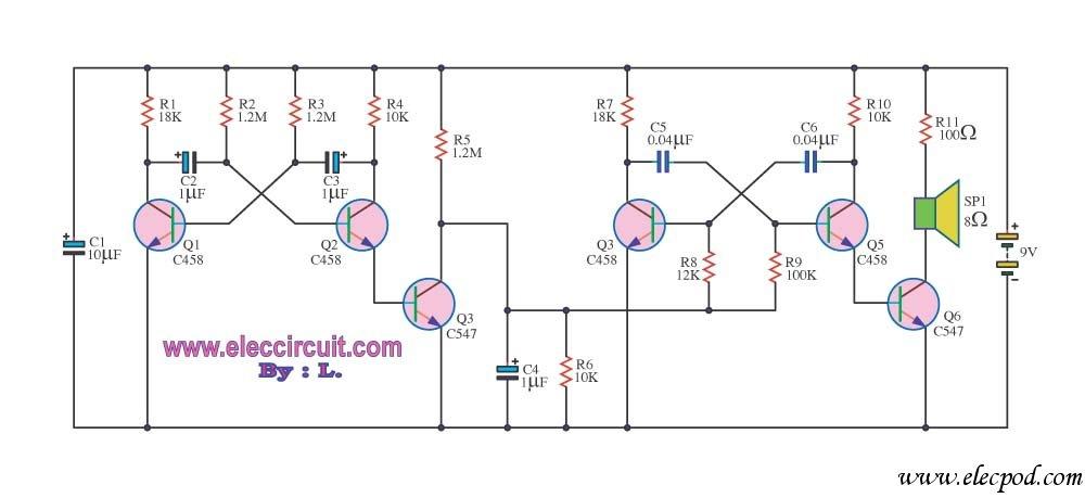
This circuit produces a siren-like sound similar to that of ambulance sirens. Unlike traditional ambulance siren circuits that typically use an IC 555, this design employs transistors, making it more economical and easier to customize. The operation of the...
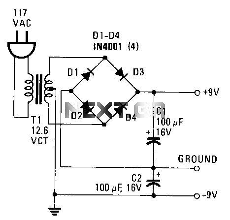
This power supply provides both +9 V and -9 V outputs to replace two 9-V batteries. The rectifier circuit consists of two separate full-wave rectifiers, each connected to the secondary winding of the transformer. The first full-wave rectifier, made...
All resistors have a tolerance of 5 or 10 percent and are rated for 1/4 watt. All capacitors have a tolerance of 10 percent and are rated for 35 volts or higher. This circuit effectively amplifies the output of...
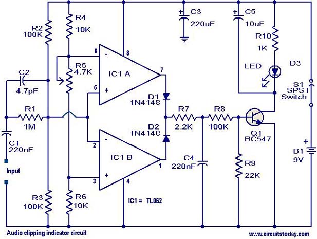
This circuit is designed to detect clipping in a specific waveform. Clipping occurs when the amplitude of a waveform decreases before reaching its expected limit. The circuit activates an LED as an indication that the tested signal is experiencing...
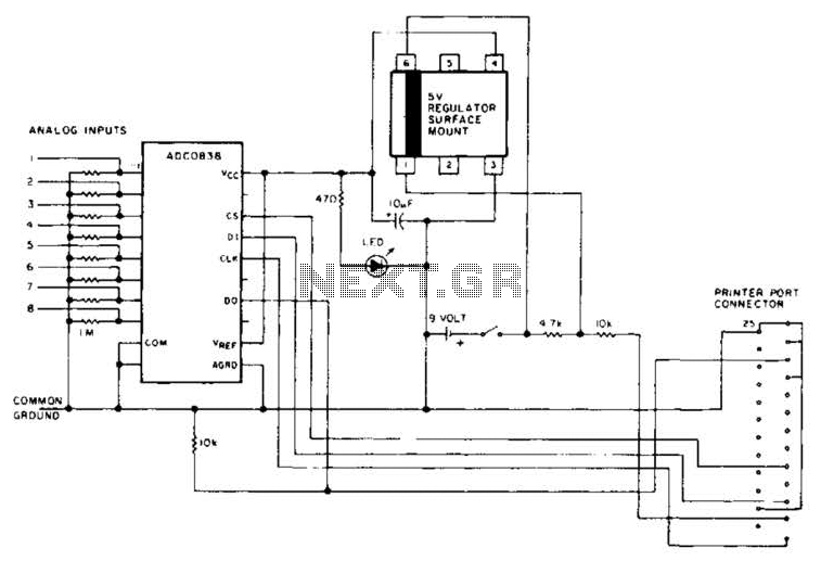
An A/D converter by National Semiconductor (ADC0838) converts 0 to 5 V analog inputs into a digital data format. A 9 V battery is utilized. The converter connects to the pointer port connector through a 25-pin connector. The ADC0838 is...
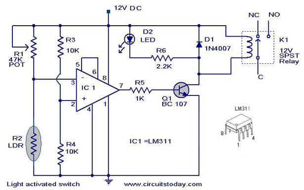
A simple light-activated switch circuit with a diagram and schematic using IC LM311 wired as a voltage comparator and an LDR that acts as a light sensor. The described circuit utilizes the LM311 integrated circuit, which functions as a voltage...
Warning: include(partials/cookie-banner.php): Failed to open stream: Permission denied in /var/www/html/nextgr/view-circuit.php on line 713
Warning: include(): Failed opening 'partials/cookie-banner.php' for inclusion (include_path='.:/usr/share/php') in /var/www/html/nextgr/view-circuit.php on line 713