
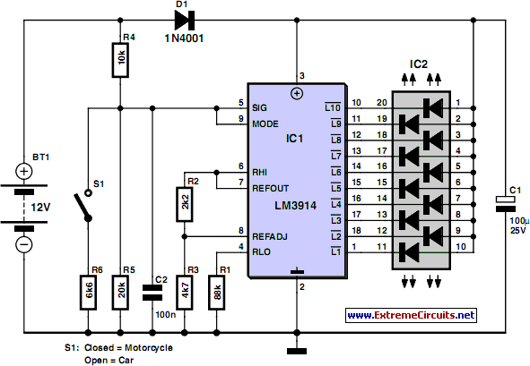
Audio clipping indicator circuit
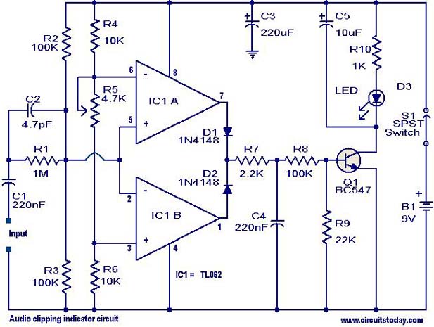
This circuit employs a window comparator configuration to effectively monitor signal integrity by detecting clipping events. The operational amplifiers in the TL082 IC serve as the core of the detection mechanism. Clipping is characterized by the inability of an amplifier to accurately reproduce input signals, resulting in distortion, which this circuit aims to identify.
The positive and negative peak detection is achieved through the op-amps, which compare the input signal against predefined threshold levels set through the potentiometer R1. When the signal exceeds these thresholds, the op-amps output a high signal that is processed by diodes D1 and D2. These diodes ensure that only the relevant signals are passed to the base of transistor Q1, which acts as a switch to control the LED indicator.
Capacitor C5 plays a crucial role in the circuit by providing a time delay that allows for the detection of transient clipping events. This feature is particularly important in audio applications where signals can change rapidly, and brief periods of clipping can be easily overlooked without this delay.
The versatility of this circuit makes it suitable for use in a wide range of audio equipment, including mixers, power amplifiers, and preamplifiers. By monitoring for clipping, users can take corrective measures to prevent distortion, ensuring optimal performance of audio systems. The adjustable threshold provided by potentiometer R1 allows for customization based on specific application requirements, making the circuit adaptable to various signal conditions.This circuit can be used to identify whether there is a clipping in a particular wave form. Clipping is a phenomenon in which the amplitude of a particular waveform drops before it reaches the expected limit. This circuit glows an LED as an indication if the signal under test has clipping. The circuit is very useful in sorting out distortion probl ems in amplifiers. The circuit is based on a window comparator based on the two opamps inside the IC1 (TL082). The circuit detects the positive or negative peak value reached by the input signal. The output of the opamp is combined by the two diodes D1 & D2 and drives the transistor Q1 to glow the LED. The capacitor C5 is employed to induce a small time delay in order to detect very fast and short peaks.
The POT R1 can be used to set the level of clipping at which the LED has to glow. The circuit can be used with almost all sorts of mixers, power amplifiers and preamplifiers. 🔗 External reference
Related Circuits
The microphone preamplifier circuit design presented in this schematic utilizes the SSM2015 component manufactured by Precision Monolithics Inc. (PMI). This component provides high amplification with low noise characteristics (1.3nV/f). The design is configured to handle differential input signals and...
The circuit depicted in the figure includes IC1 and C1, which form a low-frequency oscillator operating at approximately 400 Hz. IC2 and C3 are configured to create a frequency oscillator around 37 MHz. The low-frequency signal is output from...
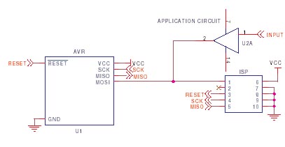
It is crucial to design the PCB layout correctly to enable seamless In-System Programming (ISP) of AVR microcontrollers. This guide addresses common issues encountered and provides typical AVR ISP circuit schematics. It focuses on Serial Programming, known as ISP,...
Camping today often involves various electronic accessories for daily activities or entertainment. Typically, a portable battery charger and a power inverter are used to ensure a well-organized campsite where both adults and children can comfortably use their electronic devices....
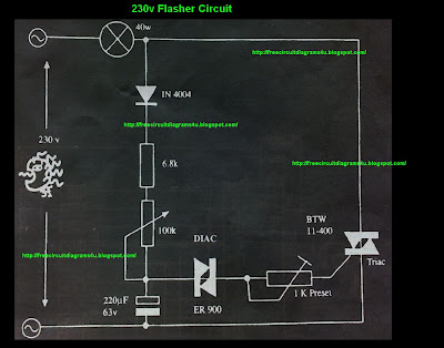
This circuit operates with 230V and can be used to decorate parties. It features a DIAC ER 900 and a TRIAC BTW 11-400. The circuit utilizes a DIAC (Diode for Alternating Current) and a TRIAC (Triode for Alternating Current) to...
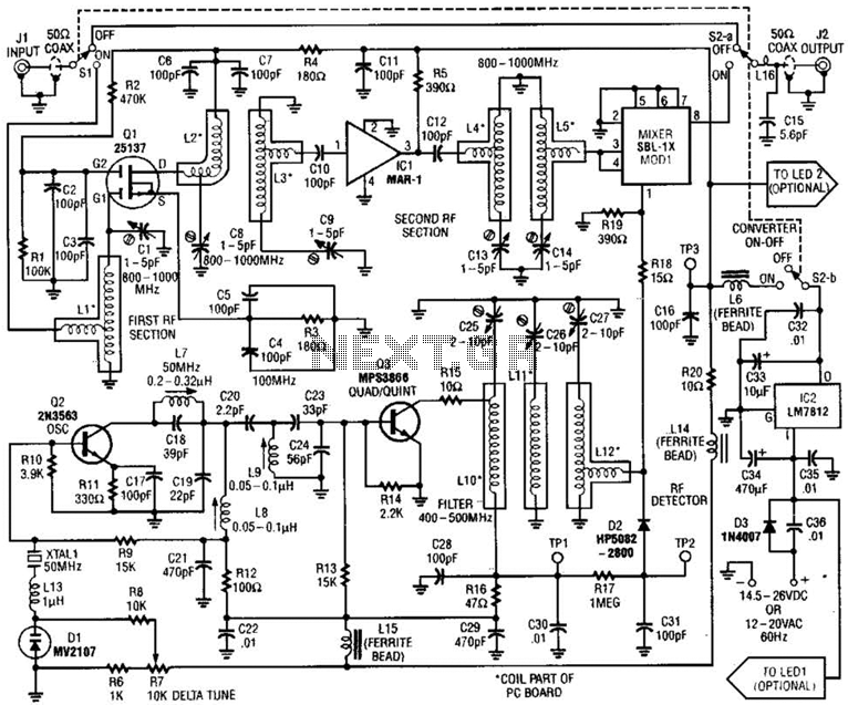
This converter allows the reception of frequencies ranging from 800 to 1000 MHz on any scanner that operates within the 400 to 500 MHz range. The converter can be configured to cover either the 800 to 900 MHz band...