
75 meter qrp ssb transceiver
The transceiver circuit operates by efficiently managing the signal flow during both receiving and transmitting modes. The four-element 1500-ohm crystal BPF is crucial for filtering the desired frequencies, ensuring that only the relevant signals pass through to the amplifiers. The use of the SA602 integrated circuits allows for effective mixing and amplification of the RF signals, while the 2N2222 transistor provides significant gain to enhance weak incoming signals.
The LM386 serves as a low-voltage audio amplifier, which is essential for driving the speaker. The automatic gain control implemented via the BS170 FET dynamically adjusts the gain of the LM386 based on the output signal level, preventing distortion and ensuring consistent audio output levels regardless of variations in input signal strength. The rectification and filtering process ensures that the AGC circuit responds accurately to the audio signal variations, allowing for smooth operation during transmission and reception.
The entire setup is designed with careful attention to impedance matching, particularly with the 50-ohm antenna and the band-pass filter, to maximize power transfer and minimize signal loss. The integration of these components creates a robust transceiver capable of effective communication in various applications.In general, the transceiver switches the 4-element 1500 ohm xtal BPF ends between the inputs and outputs of the two SA602s to reverse the signal flow for R/T operation. Since no IF amplifier is used in the design, 20 dB of additional receiver gain is produced by the 2N2222 receiver RF amplifier, while automatic gain control (AGC) is produced by the peak DC swing of the
LM386 output passed through a rectifier and filtered by a capacitor and fed to the gate of a BS170 enhancement mode FET acting as a variable resistor across the input of the LM386. 50 ohm antenna feeds half-pi band pass filter (BPF, element Q=5) which feeds receive-transmit (R/T) switch which feeds 2N2222 receive RF amplifier which feeds 1st SA602 which feeds R/T switch which feeds 4-element 1500 ohm xtal BPF which feeds R/T switch which feeds 2nd SA602 which feeds LM386 which feeds 1) diode which feeds capacitor which feeds gate of BS170 which produces audio automatic gain control (AGC) and 2) speaker attenuator which feeds speaker.
🔗 External reference
Related Circuits
Having found a u664b prescaler chip (Telefunken) from an old TV tuner, I decided to build a valid frequency counter using PIC16F84. The prescaler I use is able to divide by 64 every frequency from 30 to 1300 MHz....
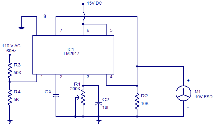
The circuit diagram of a simple capacitance meter using IC LM2917 is illustrated. The LM2917 is a high-gain monolithic frequency-to-voltage converter IC from National Semiconductors. While the primary application of the LM2917 is in tachometers, it can also be...
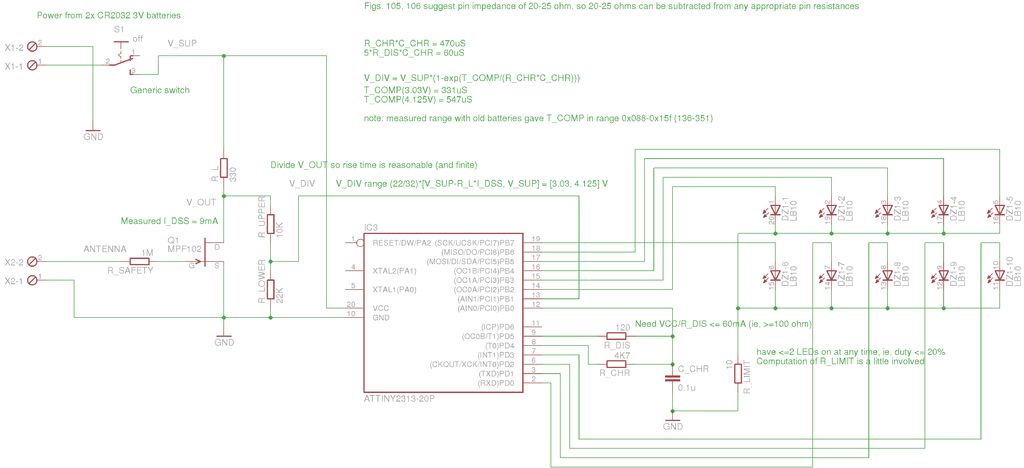
A method for measuring static electricity for a science project was sought. An old copy of "Getting Started in Electronics" by Forrest M. Mims III was referenced for guidance. To create a static electricity measurement circuit, a simple design can...
When an antenna is attached, or even if not, in the presence of a strong RF field, the field strength meter has a moving coil meter to indicate relative field strength. The box holds a Schottky diode detector, a...

This is a simple design of an audio level meter. The circuit utilizes a single integrated circuit (IC) and a minimal number of external components. It is based on the LM3915, which functions as the controller for the audio...
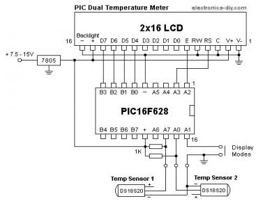
This is a simple-to-build PIC temperature meter that allows for simultaneous temperature measurement in two different locations. Such a useful and powerful circuit can be constructed with minimal components while offering extensive possibilities. This is made feasible by utilizing...