
Microcontroller interface electrometer

To create a static electricity measurement circuit, a simple design can be implemented using a high-impedance voltmeter or an analog meter. The circuit can be constructed using basic electronic components such as resistors, capacitors, and a sensitive meter.
The core of the circuit involves a high-value resistor, typically in the range of 1 MΩ to 10 MΩ, which is connected in parallel with the meter. This resistor allows the circuit to pick up small static charges without significantly discharging them. A capacitor can be added in parallel to the meter for smoothing the readings and preventing rapid fluctuations caused by transient static discharges.
To enhance the sensitivity of the measurement, a field-effect transistor (FET) can be incorporated. The FET acts as a high-impedance buffer, allowing the circuit to detect minute static charges. The gate of the FET can be connected to a conductive plate that collects static electricity from the surrounding environment.
The output from the meter can be calibrated to provide a readable voltage proportional to the static charge detected. Care should be taken to ensure that the circuit is properly shielded to avoid interference from external electromagnetic fields, which can affect the accuracy of the readings.
This circuit can serve as an educational tool for understanding static electricity and its measurement, providing practical experience in electronics for the student involved in the project.My daughter wanted a way of measuring static for her science project. While scanning through an old copy of Getting Started in Electronics by Forres.. 🔗 External reference
Related Circuits
An alphanumeric low-cost LCD display is essential for many small and large projects to display various types of information. The Hitachi HD44780 chipset-based 16x2 character LCD is very affordable and easily available in the local market. This project covers...
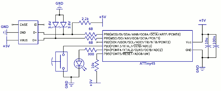
The project involves a trigger programming solution using a built-in pushbutton. The approach taken was to integrate a small USB keyboard circuit into the pen's interface. A proposed method for the pushbutton to trigger a programming command included adding...
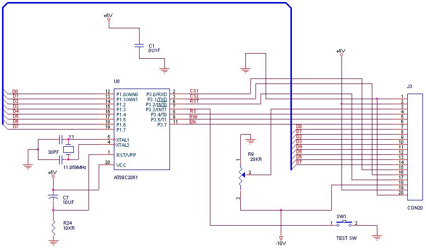
How can graphical LCDs be controlled using a microcontroller? Is there any datasheet available? Graphical LCDs (Liquid Crystal Displays) are widely used in various electronic applications for displaying complex graphics and text. To control these displays with a microcontroller, several...
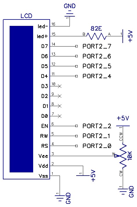
The circuit utilizes a total of seven pins from the microcontroller's GPIO. Consequently, the LCD module requires only one port out of four available. The EN line, known as "Enable," is a control line that indicates to the LCD...
This circuit is designed to produce DMX output for entertainment lighting from a PC. It offers flexibility in circuit configurations. By opting for no isolation, the setup requires only a PIC microcontroller and a standard RS-485 driver, with an...
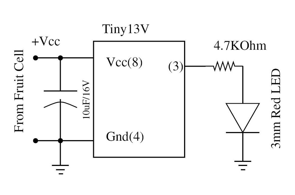
Wire the circuit diagram shown here on a breadboard. The choice of V type of AVR is important. For example, Tiny13V is very appropriate for such an application. To successfully implement the circuit diagram on a breadboard, several considerations must...