
PIC Dual Temperature Meter by PIC16F628
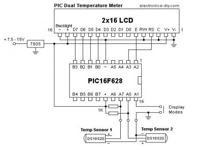
The PIC temperature meter circuit utilizes the PIC16F628 microcontroller, which serves as the central processing unit for data collection and display management. The microcontroller is programmed to interface with two DS18S20 digital temperature sensors, which communicate with it via a single data line using the 1-Wire protocol. This protocol allows for the connection of multiple sensors on the same data line, facilitating the simultaneous measurement of temperatures from different locations.
The DS18S20 sensors convert the ambient temperature into a digital signal, which is then sent to the microcontroller for processing. The microcontroller interprets this data and sends it to the 2G-16 character LCD display, where it is presented in a user-friendly format. The LCD is capable of displaying temperature readings in degrees Celsius or Fahrenheit, depending on the firmware configuration.
Power supply considerations for this circuit are essential, as the PIC16F628 microcontroller and the DS18S20 sensors require a stable voltage for accurate operation. A regulated power supply circuit can be included to ensure that the system operates reliably under varying input conditions.
The design of the circuit allows for flexible placement of the temperature sensors, as they can be located at significant distances from the main circuit board without compromising the integrity of the data transmission. This capability is particularly advantageous in applications where temperature monitoring is required in multiple environments, such as in HVAC systems, laboratories, or outdoor settings.
Overall, the PIC temperature meter is an innovative solution that combines simplicity, efficiency, and versatility, making it an excellent choice for temperature measurement applications. The use of digital sensors and a customizable microcontroller enhances its functionality and adaptability to various user needs.This is extremely simple to build PIC Temperature meter that allows to measure temperature in two different locations at the same time. Never before such a useful and powerful circuit could be built with so little components and yet provide endless possibilities.
This is all possible thanks to the use of PIC16F628 microcontroller and 2G—16 charact er LCD display that act like a small computer which can be customizable thanks to upgradeable hex firmware. Presented PIC temperature meter uses two very exciting DS18S20 digital temperature sensors that come in convenient TO92 package.
Unlike regular sensors where temperature readings are passed as varying voltage, DS18S20 passes temperature information in a digital format as data. This brings many new possibilities and enables to pass temperature information over much longer distances just over a two wire cable.
With this temperature can be measured in different locations at the same time and away from the main circuit board. With regular sensors which rely on the varying voltage cables must be as short as possible because longer wires introduce stray resistance that bring unreliable readings.
🔗 External reference
Related Circuits
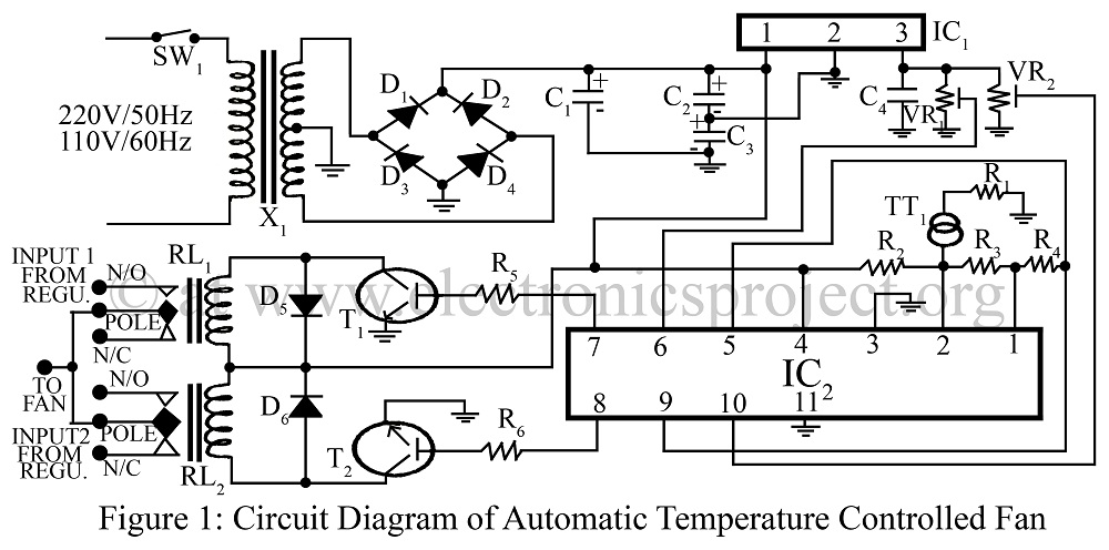
An automatic temperature-controlled fan regulates the fan speed based on temperature variations using the temperature transducer AD590 and an op-amp LM324 circuit diagram. The automatic temperature-controlled fan circuit utilizes the AD590 temperature transducer, which provides an output voltage that is...
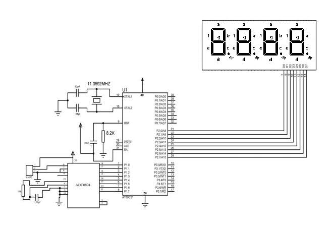
The temperature sensor was connected to 8 LEDs provided with the DeccanRobots package, successfully displaying the temperature in binary format. However, when attempting to use a microcontroller with a program designed to output the temperature on 4 seven-segment displays...
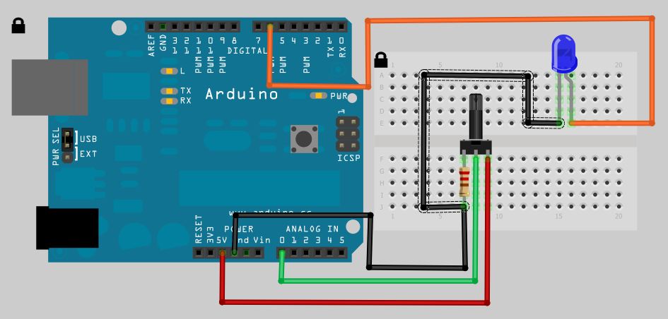
The analog to digital sketches have been extensively covered using various components. To progress to more complex circuits and concepts, it is essential to understand these simpler ones. This tutorial will not delve as deeply as others due to...

The output voltage of a thermocouple is converted into a frequency that is measured by a digital frequency meter. The output signal from the thermocouple is proportional to the temperature difference between the hot junction and a reference thermostat...

A highly sensitive picoammeter (−1 V/pA) utilizes an amplifier configured in the inverting or current summing mode. It is crucial to eliminate stray currents from entering the current summing mode. The circuit stabilizes to within 1% of its final...
This circuit is an ETHERNET controller I use the PIC18F452 and the mikroC C Compiler. I use also the JAVA SCRIPT information you can get from www.w3school.com I Control 8 outputs throw the WEB and transfer time information also....