
807 Tube Triode Connected
The amplifier circuit comprises several key components that work together to achieve optimal performance. The input stage typically includes the 6DJ8 tubes configured as a differential amplifier. These tubes are known for their low noise and high gain characteristics, making them ideal for audio applications. The phase splitter configuration allows for the conversion of a single-ended input signal into a balanced output, which is essential for driving the push-pull stage effectively.
The inclusion of the 1N5312 and 1N5313 diodes as current limiters in the phase splitter enhances the stability of the circuit by preventing excessive current flow that could damage the tubes. The SIMetrix current source serves as an adequate substitute for the missing Spice model, ensuring that the design remains functional and reliable.
The proposed modifications to the resistor values and the addition of the filter capacitor are critical in optimizing the performance of the amplifier. By adjusting the cathode resistors from 33K to 18K, the biasing of the tubes is altered, allowing for improved linearity and reduced distortion. The introduction of the 4.7K resistors and the 47uF capacitor further stabilizes the voltage supply to the driver tubes, ensuring consistent operation under varying load conditions.
Utilizing the DN2540 MOSFET as an adjustable current mirror for the plates of the phase splitter presents a modern approach to enhancing amplifier performance. This component's high voltage rating and low on-resistance contribute to lower distortion levels and increased gain, making it a valuable addition to the design. The careful consideration of headroom and power supply design ensures that the amplifier can handle dynamic audio signals without clipping or distortion.
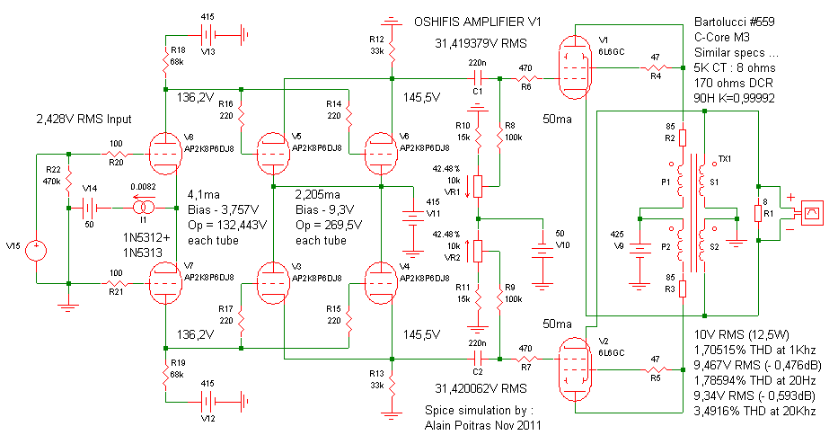
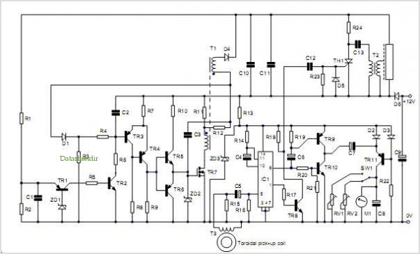
Overall, this amplifier design exemplifies a thoughtful integration of traditional tube technology with modern electronic components, resulting in a robust and high-performing audio amplifier suitable for various applications. This is a very nice amplifier design and it is very difficult to improve it. I am glad about the results because that's a very good way to verify my 6DJ8 and 6L6GC Spice models, like I tell you before, the 6L6GC and 807 have very close caracteristics and I get very close results to what you schematic said It is a really good idea to use the 1N5312 and 1N5313 diodes current limiter for the phase splitter current mirror but I don't have their Spice model so I just use the incorporated SIMetrix current source, it does exactly the same thing . This is something you should take care of as soon as possible because I know the 6DJ8 are very expensives ... The phase splitter tubes operation point look very good to me so I draw a corrected version with a close operation point for the driver too and a safe Va under 130V.
Like you can see, you just have to change the 33K cathode resistors for 18K (R12 and R13) and add two 4,7K 2W (or more) resistor (R23 and R24) and a 47uF filter capacitor (C3) to get a 268,8V supply for the driver tubes. There is just a little bit more distortion this way but nobody will notice any differences for sure. Of course, the distortion is a little bit higher but it is so simple ... However, there is a simple way to improve it, since you already use a current mirror for the splitter cathodes, why not use adjustable ones for their plates, using a good "TO220 high voltage DN2540 power depletion MOSFET" as current limiter ...
It improve the distortion and the gain ... It is still very simple and cheap, a DN2540 cost about 2,50$ and last for life but each time you replace your four 6DJ8 drivers, it cost you over 100$, think about it ... A phase splitter like that just need a 200V supply or a little more if necessary so you can get a better filtered supply for this stage.
I left a 48V "headroom" for a signal up to 34V RMS plus 15,8V for the DN2540 Vds, it is plenty enough, just provide a very small heatsink for each of them will help if they get too hot. 🔗 External reference
Related Circuits
The concept of an AC model for the triode is presented, and the equivalent circuit technique is described. Theoretical calculations for amplifier gain and frequency response are derived and compared to simulation results in the SPICE3 environment, showing good...
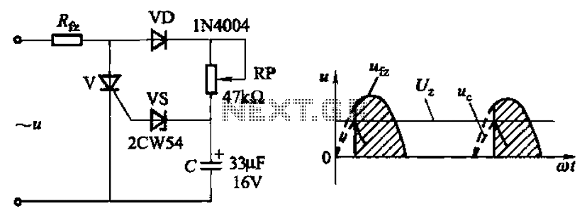
Circuit characteristics: A simple phase shift range of 180 degrees; exhibits good linearity and control accuracy compared to the first two options, making it suitable for low voltage applications, particularly in less demanding electroplating and electrolysis power supplies. The described...
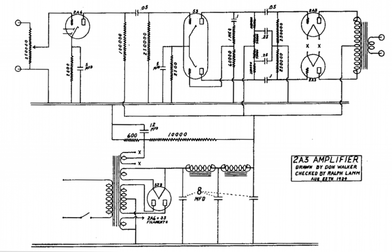
Two circuits of audio tubes amplifiers. Additional Content: The indicated schematic represents two circuits of audio tube amplifiers. These amplifiers are primarily designed to increase the amplitude of audio signals that pass through them. They are typically used in...
The most effective way to understand space-charge tubes is to examine actual circuits. Review the online circuits provided below, and check if any older print articles are available from friends or personal collections. After familiarizing yourself with the material,...
The DS2422 temperature and data logger integrates the essential functions of a comprehensive data logger into a single chip. It features a temperature sensor, a real-time clock (RTC), memory, a 1-Wire interface, and a serial interface for an analog-to-digital...
This file contains information on tube transconductance, including its computation and applications. It is considered one of the best descriptions available, presented in a straightforward manner without delving deeply into mathematics. This document, authored by T. Slonczewski in the...