
Space Charge and Low-Voltage Tubes

To avoid grid confusion, the first grid, which is closest to the cathode and functions as the control grid in conventional tubes, should be connected to 12V. In cases where a conventional tetrode or pentode is utilized in space-charge mode, ensure that 12V is applied to the control grid, using the screen grid as the control grid. While pentode suppressor grids are generally internally connected to the tube cathode, if the suppressor grid is accessible via a pin, applying 12V to it may enhance gain in certain circuits by having two grids accelerate electrons toward the weakly charged plate.
Biasing in these circuits differs significantly from biasing in circuits with B+ voltages in the 150-200V range. It is crucial not to simply substitute a 12V tetrode or pentode into a circuit designed for 180V tubes. Consulting the articles listed below is recommended, as they often present simpler yet different designs. If possible, obtain a copy of an early 1960s RCA receiving tube handbook, which contains technical specifications for various tubes and reference model circuits, typically car radios. Antique Electronic Supply in Arizona offers reprints of the 1959 and 1973 editions, both of which are valuable resources. The 1973 edition includes all the aforementioned 12V tubes.
It is essential to recognize that many standard high-voltage tubes can be effectively operated with DC voltages as low as 3V on the plates. Some tubes can function in "space-charge" mode, utilizing the first grid as an input. The challenge with tubes is that extracting power from a tube circuit necessitates high voltage operation. If significant output power is not required, such as for a loudspeaker, and low plate current is acceptable, plate voltage can be maintained under 20V, often below 10V. In radio receiver construction, this typically necessitates the use of high-impedance headphones for audio output, defined as 600 ohms or more at audio frequencies, with higher impedance being preferable. These high-impedance headsets are increasingly difficult to find; while Antique Electronic Supply previously sold them, they have not appeared in catalogs from 2007-2008 onwards. However, they can often be located on eBay or through military surplus outlets like Fair Radio Sales.
Crystal earphones, which also possess high impedance, can be utilized, but they have a limitation: they do not conduct DC. In many older circuits, the plate voltage flows through the headphones, necessitating the use of dynamic headsets equipped with wire-wound transducers rather than crystal transducers. For instance, the schematic for KB7NRN's 18V radio illustrates that a crystal earphone is incompatible with this circuit, as well as any circuit that routes B+ to the tube's plate through the headset. Many circuits found in literature specify battery voltages of 45V, 67.5V, or 90V, which are still available but can be costly. However, numerous circuits will function adequately at significantly lower voltages. For example, the 3V4 BCB receiver from Harry Zarchy's kid-hobby book, "Using Electronics," incorporates a 100K resistor in series with the circuit.The best way to get a sense for space-charge tubes is to study some real circuits. Look at the online circuits listed below, and see if you (or one of your friends) have any of the older print articles listed after the online articles. That done, choose a simple circuit for a "learning project" and just have at it! That said, here are some tips: B e aware that these tubes (with the possible exception of the type 8056 nuvistor) draw a lotof current at 12V, sometimes almost half an amp. (Virtually all of this goes into heating the cathode. ) If you put three or four in a circuit, you had better be able to supply 12V at two or three amps. This is easy in a car; not always so easy on a test bench. I don`t recommend making up space-charge portable radios using AA cells! Avoid grid confusion! The first grid (the grid physically closest to the cathode; what in conventional tubing is called the control grid) should be tied to 12V.
If you`re using a conventional tetrode or pentode in space-charge mode, make sure you put 12V on the control grid, and use the screen grid as the control grid. Pentode suppressor grids are almost always tied internally to the tube cathode, but if the suppressor grid comes out separately to a pin, try putting 12V on the suppressor as well.
This may allow greater gain in some circuits, as you have two grids accelerating electrons toward the weakly charged plate. Biasing is not anything like biasing when your B+ is in the 150-200V range. Don`t just drop a 12V tetrode or pentode into a circuit designed for a 180V tubes. Try to find some of the articles I list below and study the circuits. It`s not that they`re more complex. (Generally, you`ll find them simpler!) They`re just different. If you possibly can, find a copy of an early 1960`s RCA receiving tube handbook. This will give you tech specs on all the tubes, plus a couple of "reference model" circuits (usually car radios) to stare at.
Antique Electronic Supply in Arizona sells reprints of the 1959 and 1973 editions, both of which are worth having. The 1973 edition (probably one of the last) has all the 12V tubes listed above. Keep in mind that a lot of "ordinary" high-voltage tubes can be used very effectively with DC voltages as low as 3V on the plates.
Some of these tubes can be operated in "space-charge" mode with the first grid used as an The problem with tubes generally is that taking power out of a tube circuit requires operating at a high voltage. If you don`t need significant output power (say, for a loudspeaker) and can settle for very low values of plate current, you can use plate voltage values under 20V, and often less than 10V.
When building radio receivers, this generally requires using high-impedence headphones for audio output, where "high-impedence" means 600 ohms or more at audio, the higher the better. Such headsets are getting increasingly hard to find; Antique Electronic Supply used to sell them, but do not show them in the 2007-2008 catalog or later.
I do see them regularly on eBay. You can also try military surplus outlets like Fair Radio Sales. Crystal earphones are also high impedence and can be used, with one gotcha: They do not pass DC. In many older circuits, the plate voltage passes through the headphones, which requires a dynamic headset (that is, one with wire-wound transducers) rather than a crystal transducer. For an example, scroll down to t he schematic for KB7NRN`s 18V radio. A crystal earphone will not work in this circuit, nor any circuit that passes B+ to the plate of the tube (or anywhere else) through the headset.
Many of the circuits you`ll find in books and magazines specify 45V, 67. 5V, or 90V batteries, which can still be had but are expensive. A lot of those circuits will work just fine on much lower voltage. For example, I built the 3V4 BCB receiver from Harry Zarchy`s kid-hobby book Using Electronics, and the circuit has a 100K resistor in series wi 🔗 External reference
Related Circuits
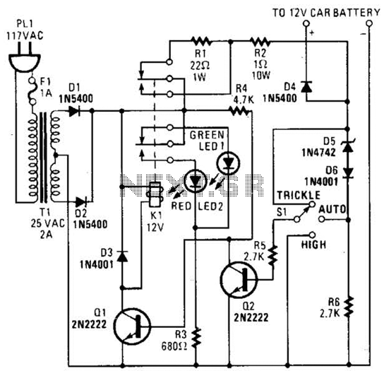
The circuit is capable of supplying either a trickle charge (50 mA) or a high-current charge (1 A). Users can select either charging method or an automatic mode that initially trickle charges a battery if it is particularly low...
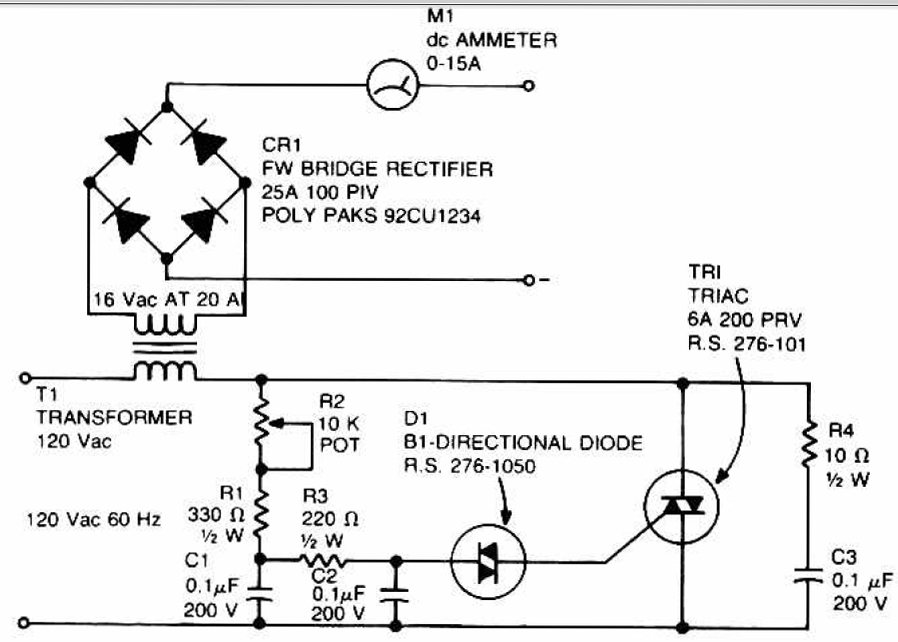
This circuit can be used to charge accumulator and cell batteries. It features a very stable output that extends the battery life and maximizes the added battery capacity. The charging process is also quite fast, optimizing the time required...
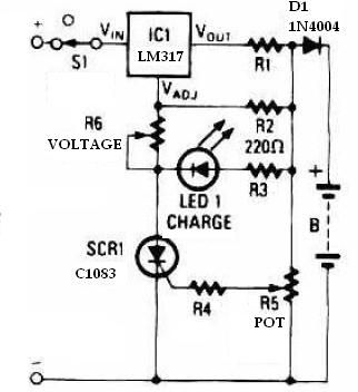
This schematic circuit for a battery charger consists of very few components but operates effectively. When power is applied to the circuit, SCR1 remains off, preventing any bias current from flowing to ground. The LM317 voltage regulator is connected...
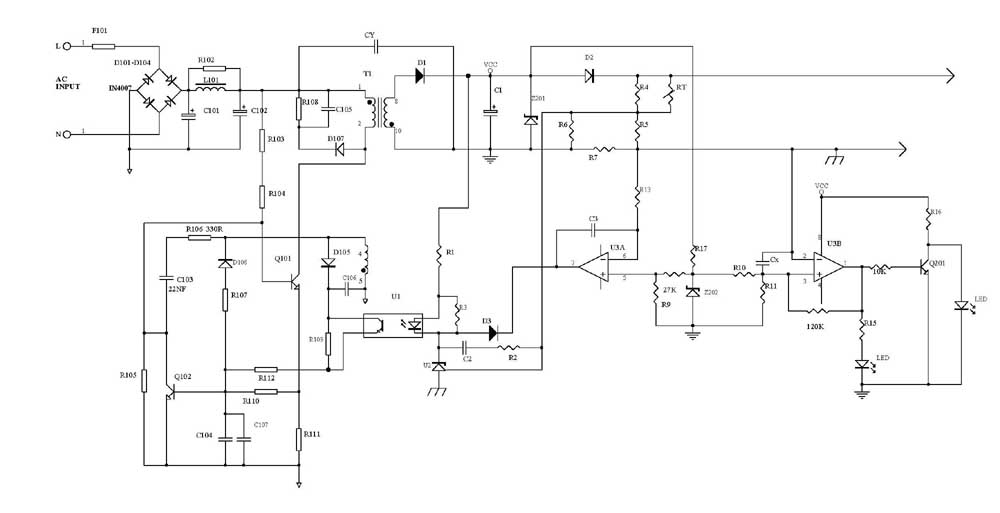
Several schematic drawings of battery charger circuits are provided. These circuits cover 5W to 200W for NiCd, NiMH, Lead-Acid, Li-Ion/Polymer, and LiFePO4 battery packs. The charger circuit files aim to assist users in selecting the appropriate chargers and to...
Charge your iPod without connecting it to a computer! Using the USB port on your computer to charge your player's batteries is not always practical. To facilitate the charging of an iPod without the necessity of a computer, a dedicated...
Alkaline Battery Charger. This circuit was specifically designed to recharge alkaline cells. The unusual connection of the transistor in each charging unit will cause it to oscillate. The alkaline battery charger circuit is engineered to effectively recharge alkaline batteries, which...