
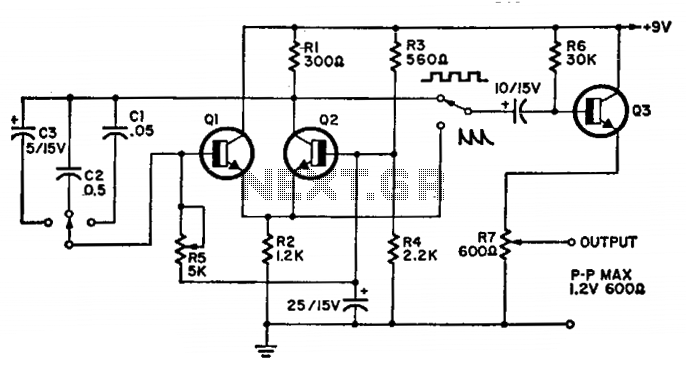
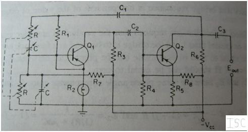
Basic RF Oscillator

To implement a circuit capable of receiving the specified FM signal, a standard FM radio receiver can be utilized. The coupling of the signal to the main stage of the receiver is achieved through a disc capacitor, which is selected to have a capacitance value of approximately 0.1 µF.
In this configuration, the disc capacitor serves to block any DC component of the incoming signal while allowing the AC component, which carries the information, to pass through. This is crucial for maintaining the integrity of the FM signal during the reception process. The capacitor must be rated to handle the frequency range of the FM broadcast, typically from 88 MHz to 108 MHz, ensuring that it does not introduce excessive loss or distortion.
The main stage of the FM receiver typically includes an RF amplifier, a demodulator, and an audio amplifier. The RF amplifier boosts the weak incoming signal, improving the overall sensitivity of the receiver. The demodulator then extracts the audio information from the modulated carrier wave, converting it into an audio signal that can be amplified further by the audio amplifier for playback through speakers or headphones.
Proper grounding and shielding are essential in this circuit to minimize noise and interference, which can degrade the quality of the received signal. Additionally, the layout of the circuit should be designed to reduce parasitic capacitance and inductance, which can affect the performance of the FM receiver.
In summary, the use of a 0.1 µF disc capacitor for coupling the signal to the main stage of an FM radio receiver is a critical design consideration that ensures effective signal processing and high-quality audio output.You ought be able to pick up its signal with a standard FM radio receiver. The signal in ought be coupled by a disc capacitor of about 0. 1 uF to stage in main of it. 🔗 External reference
Related Circuits
A simple variable frequency oscillator utilizing a 555 timer IC to generate a square wave frequency that can be adjusted using a potentiometer. The circuit operates primarily on the principles of astable multivibrator configuration using the 555 timer IC, which...
Here the popular 555 timing IC is wired as a monostable. The timing period is precise and equivalent to: 1.1 x R1 x C1. With component values shown this works out at approximately 1.1 msec. The output duration is...
The circuit operates within a frequency range of 15 Hz to 30 kHz and serves as a function generator. The 2N2926 transistor or its equivalent can be utilized in this design. This function generator circuit is designed to produce a...
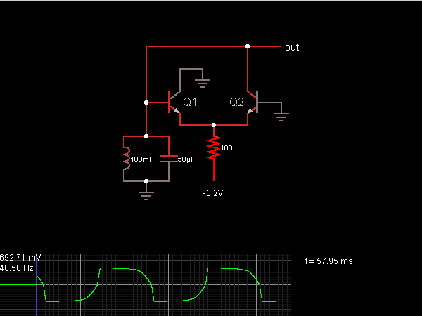
When the oscillator starts, Q2 is in a conducting state; the current flows from the capacitor, charging it until the voltage across it is sufficient to allow current to flow through the inductor. As the current through the inductor...
This article explains the construction and working of feedback oscillators, with a detailed description of the Wien bridge oscillator and phase shift oscillator, along with their circuit diagrams, basic components, and practical applications. Oscillators are electronic devices that produce...
The beat frequency oscillator (BFO) is essential for receiving continuous wave (CW) signals. Since CW signals lack an audio modulation component, it is necessary to introduce one. The functions of the RF amplifier, mixer, local oscillator, and IF amplifier...