
Simple variable frequency oscillator
The circuit operates primarily on the principles of astable multivibrator configuration using the 555 timer IC, which is a versatile and widely used component in electronic applications. In this setup, the 555 timer is configured to oscillate between high and low states, producing a square wave output. The frequency of this output can be varied by adjusting a potentiometer connected to the timing components of the circuit.
The essential components of the circuit include the 555 timer IC, a resistor (R1), a potentiometer (R2), and a capacitor (C1). The values of R1 and R2, along with the capacitance of C1, determine the frequency of oscillation according to the formula:
\[ f = \frac{1.44}{(R1 + 2R2) \cdot C1} \]
where:
- \( f \) is the frequency in hertz (Hz),
- \( R1 \) is the resistance in ohms (Ω),
- \( R2 \) is the resistance of the potentiometer in ohms (Ω),
- \( C1 \) is the capacitance in farads (F).
To construct the circuit, the following steps should be followed:
1. Connect pin 1 of the 555 timer to ground.
2. Connect pin 8 to the positive supply voltage (typically between 4.5V to 15V).
3. Connect R1 between pin 7 (discharge) and pin 8 (Vcc).
4. Connect the potentiometer (R2) between pin 7 and pin 6 (threshold).
5. Connect pin 6 to pin 2 (trigger).
6. Connect a capacitor (C1) between pin 2 and ground.
7. Connect pin 3 (output) to the output load or measurement device.
By adjusting the potentiometer, the resistance value changes, thus altering the timing interval and consequently the frequency of the square wave output. This circuit can be used in various applications, including tone generation, frequency modulation, and as a clock pulse generator for digital circuits. The simplicity and adjustability of this variable frequency oscillator make it a valuable tool in both educational and practical electronic projects.Simple variable frequency oscillator. This is a very simple circuit utilising a 555 timer IC to generate square wave of frequency that can be adjusted by a potentiometer. With values given. 🔗 External reference
Related Circuits
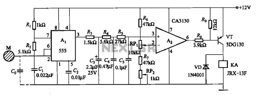
The circuit utilizes a 555 IC in conjunction with capacitors C1, C2, and a metal plate (tablet) M to create a distributed capacitance Co and resistor R1 connected to ground. Resistor R2 forms a self-excited multivibrator, while resistors R3...
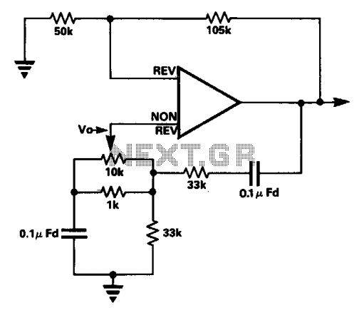
In the circuit, the frequency trimming component is configured such that the voltage across it is in quadrature with the voltage V0 from the bridge. This arrangement allows for adjustments to be made with minimal changes to the attenuation...
1 kHz RC phase shift oscillator circuit The 1 kHz RC phase shift oscillator circuit is designed to generate a continuous sine wave output at a frequency of 1 kHz. This circuit typically utilizes a combination of resistors and capacitors...
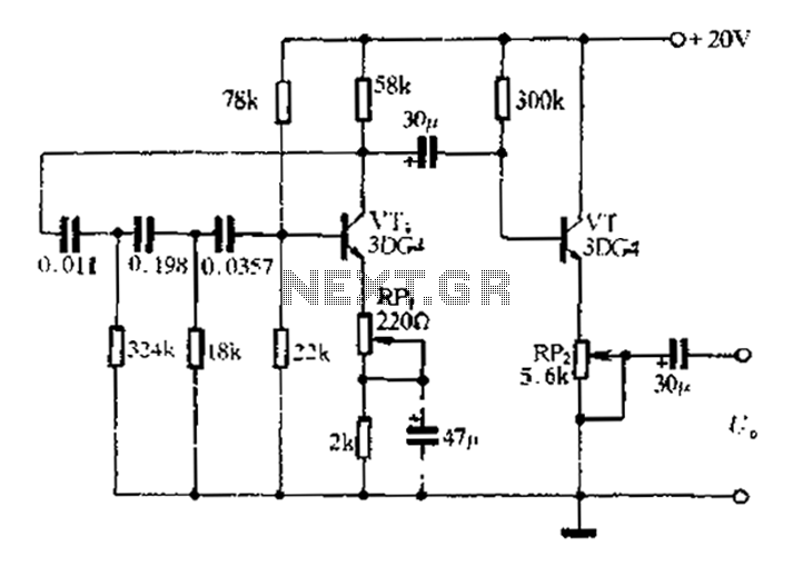
A schematic diagram of the oscillator is presented in Figure 1. The common-base transistor stage (Q1) amplifies the signal within the positive feedback loop. The positive feedback signal develops across the resistor R1, which is shared by the emitters...
This circuit is designed for applications where over-current protection is necessary. An example can be found in the model train hobby. Experienced model train enthusiasts understand that troubleshooting a short-circuit can be quite challenging. While it is relatively easy...
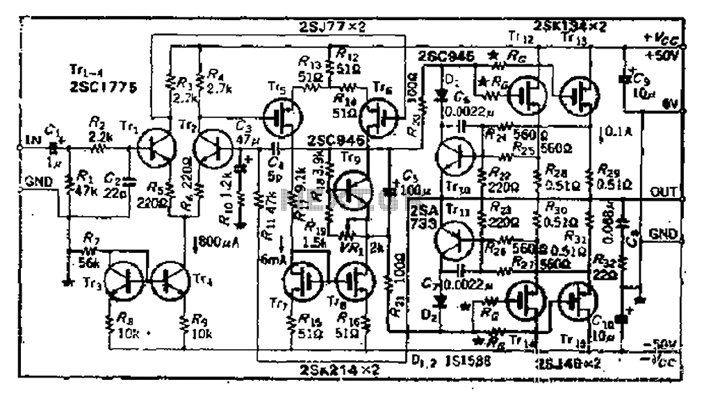
The circuit consists of three identical basic stages, with the second stage featuring a differential output from the power MOSFET, 2SJ77. A current mirror circuit utilizing 2SK214 is implemented. The operating current is 6mA; however, due to the power...
Warning: include(partials/cookie-banner.php): Failed to open stream: Permission denied in /var/www/html/nextgr/view-circuit.php on line 713
Warning: include(): Failed opening 'partials/cookie-banner.php' for inclusion (include_path='.:/usr/share/php') in /var/www/html/nextgr/view-circuit.php on line 713