
Charged Capacitor to Light an LED

The circuit design consists of a battery, a capacitor, a pushbutton switch, and an LED. The battery is connected in parallel with the capacitor, and the pushbutton switch is placed in series with the LED. When the pushbutton is pressed, it completes the circuit, allowing current to flow from the battery to both the LED and the capacitor. The LED lights up immediately as it receives power from the battery, while the capacitor begins to charge. The charging time is relatively short, typically within a few seconds, depending on the capacitor's capacitance and the battery voltage. Once the capacitor reaches its rated voltage, it becomes fully charged, and the battery continues to supply power to the LED until the pushbutton is released.
Upon releasing the pushbutton, the circuit opens, disconnecting the battery. The LED remains illuminated for a brief period as the capacitor discharges its stored energy. The discharge rate is influenced by the load (in this case, the LED) and the capacitance of the capacitor. A larger capacitor allows for a longer discharge time, making it suitable for applications requiring sustained illumination during brief power outages. The circuit can be further enhanced with additional components such as resistors to limit current, diodes to prevent backflow, or even a microcontroller for more complex control mechanisms. Overall, this simple yet effective circuit demonstrates the utility of capacitors in providing temporary power solutions in electronic applications.For this project, we are going to charge a capacitor with voltage and then have the capacitor act as a temporary power source for the circuit. After we charge the capacitor with the battery, we`re going to disconnect the battery from the circuit.
The capacitor will then act as the power source, giving current to the LED so that the LED remains on, though not being powered anymore by the battery. When the capacitor acts as the power source, it dumps its voltage much quicker than a battery does so the LED is on only for a short period of time. However, nonetheless, it still gives power to the LED so that it can remain on. This can have great real-life application in which there is a very brief shut-down in power, for instance, if the power goes out for a few seconds and then turns back on.
While the power is off, the LED or whatever desired load needs to be kept on can remain on if there is a capacitor acting as a backup power source. When the button is pressed down, closing the circuit, the battery does two jobs: it charges the capacitor up with voltage and it gives power to the LED, lighting it.
Once the battery is on for enough time for the capacitor to be fully charged up to 9 volts, the capacitor cannot retain any more charge. This happens in a matter of seconds. The battery, however, keeps powering the LED. Now remove your finger from the pushbutton so that the circuit is now open. Now the battery is disconnected from the circuit, and thus can no longer power the LED. However, the LED still remains on for an extended period of time after even though the battery is disconnected.
This is because the capacitor now acts as the (temporary) power source for the circuit, giving power to the LED, so that it stays on for a short while. A capacitor does not act like a battery, because it dumps its charge very quickly, so that the LED only receives power for a few seconds.
However, if a power source goes out for a while, the capacitor can act as a temporary power source. The larger the capacitor used, meaning the greater the charge it can store, the longer it can power a device, though it takes longer to charge. If we used a 2000G‚ µF, it could power the LED for double the time, being that it can store more charge, and if we used a 4000G‚ µF, it could power the LED for 4 times longer, being that it has quadruple the charge capacity.
🔗 External reference
Related Circuits
This article is relevant only to readers whose bicycle lights are powered by a dynamo. The regulations regarding bicycle lights in the United Kingdom are stricter than in other countries, making the use of a dynamo uncommon in this...
Just to prove that transistors can also be useful in logic situations; this is a data latch and indicator which also is a data switch and has a bidirectional input/output port which can be read or switched. If the...
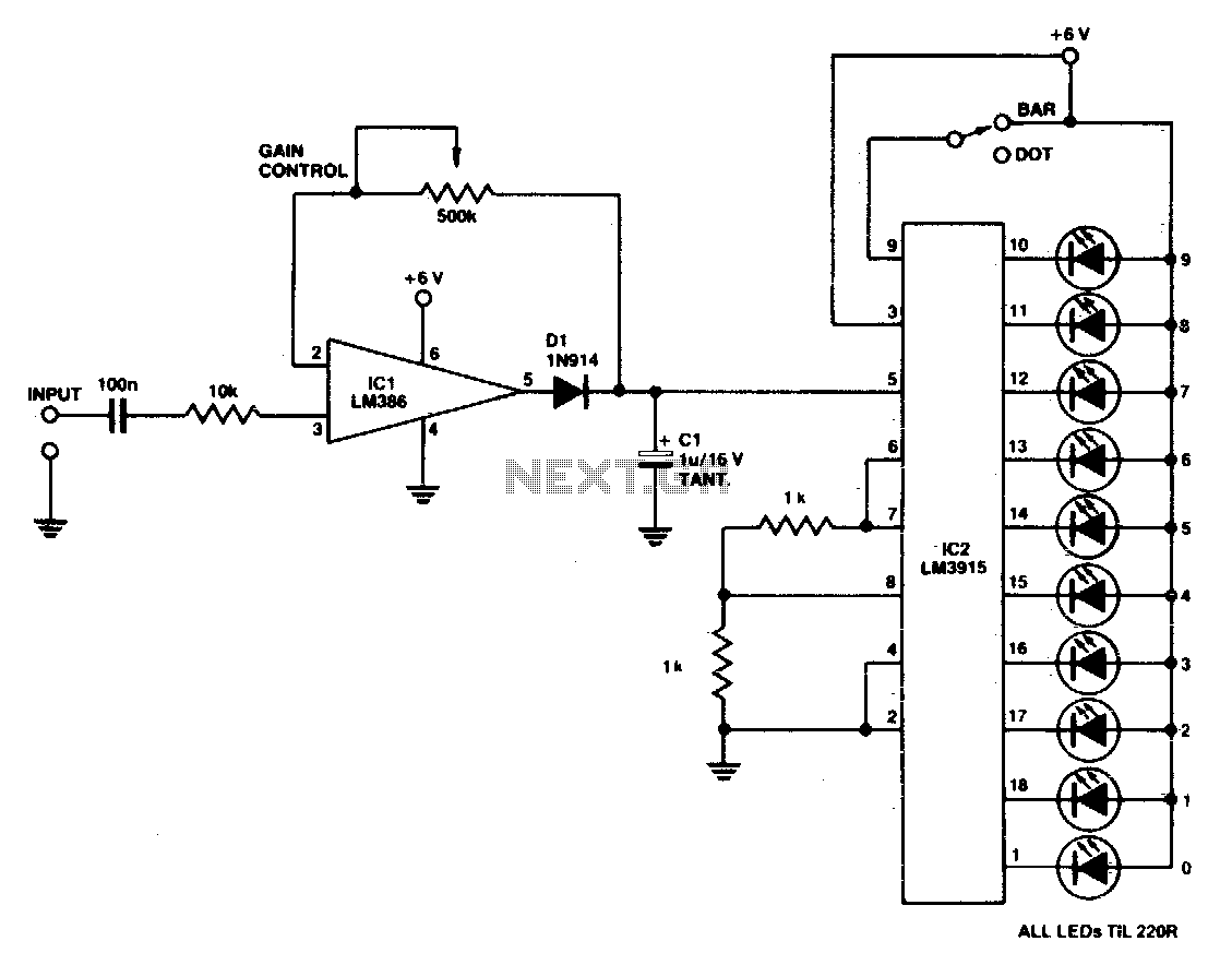
A simple power meter can be configured to provide a bar or dot display for a hi-fi system. Green LEDs are used for levels 0 to 7, yellow for level 8, and red for levels 9 to indicate peak...
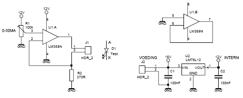
This led tester uses a power switched op-amp. The control range is about 0-30mA. Thus, all test and standard LEDs, the voltage across the LED to read. The power supply is an example lab power supply at least 15V,...
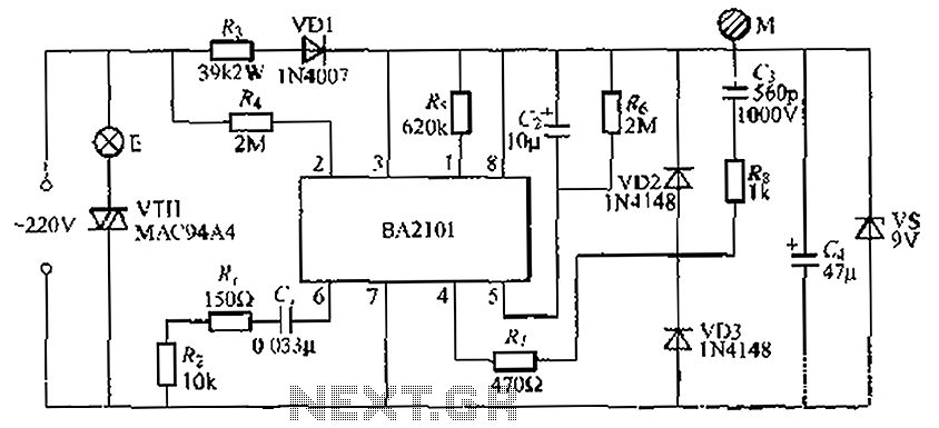
The BA2101 is a dimming controller utilizing an ASIC to create a barrel of light touch stepping. It is a non-constant lamp suitable for heir light. Each touch on the electrode sheet M can adjust the lamp brightness through...
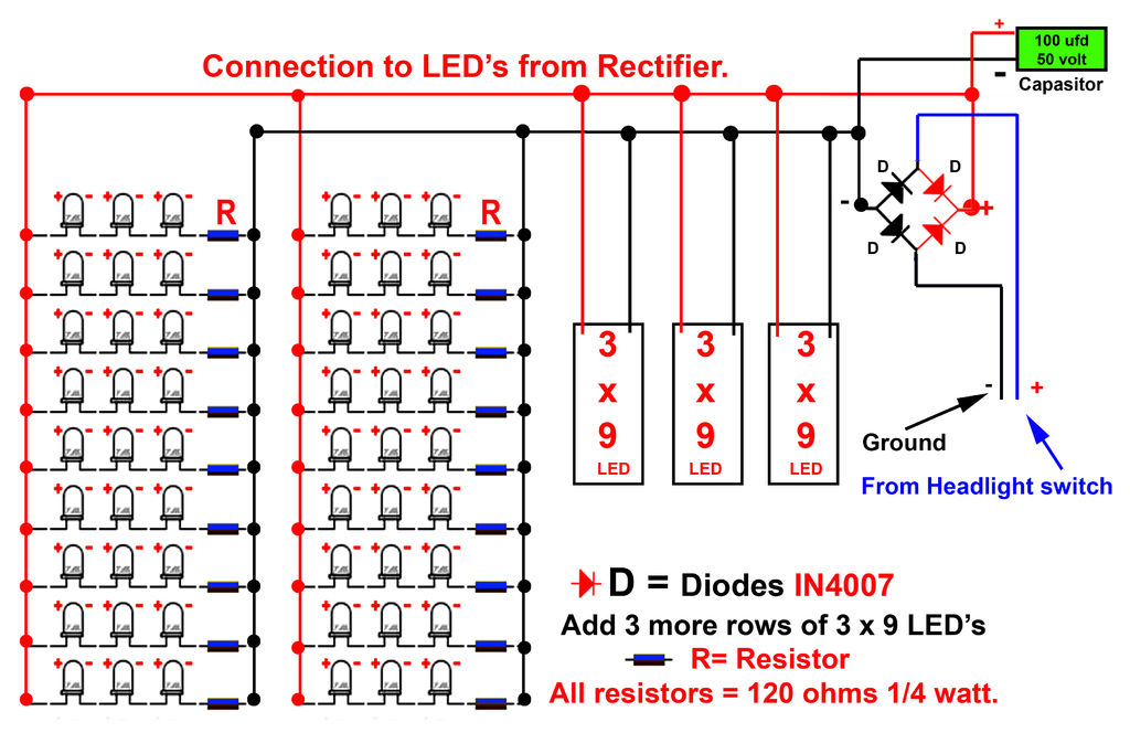
Gently bend the leads of the LEDs and, using the provided schematic circuit diagram, begin to solder. Once soldering is complete, it should... To successfully assemble the LED circuit, it is essential to follow a systematic approach. Start by preparing...