
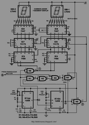
DIGITAL FUEL GAUGE

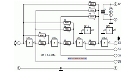
The circuit is structured to facilitate the measurement of fuel levels in various types of tanks, utilizing a digital voltmeter to provide precise readings. The integration of IC1 and IC3 forms the digital voltmeter, which translates the voltage signal from the fuel sensors into a readable percentage format. The choice of fuel sensors allows flexibility in application; the low-resistance sensor is suitable for some fuel types, while the high-resistance sensor caters to others.
IC2 plays a crucial role in signal amplification, enhancing the voltage levels received from the fuel sensors to ensure accurate readings by the digital voltmeter. The dual output configuration of IC2, with both inverting and non-inverting paths, allows for versatility in signal processing. This is particularly important for calibrating the circuit to ensure that it accurately reflects the actual fuel level, regardless of the sensor type used.
Calibration adjustments are essential for fine-tuning the circuit's response to different sensor outputs, ensuring that the displayed percentage aligns with the actual fuel quantity. This feature enhances the reliability of the circuit in various operating conditions, making it suitable for use in different vehicles or fuel storage systems.
The overall design emphasizes accuracy and adaptability, making it a valuable tool for monitoring fuel levels in real-time. The digital voltmeter's clear display provides immediate feedback to the user, enhancing operational efficiency and safety by preventing fuel shortages or overflow situations.This circuit uses a digital voltmeter (formed from IC1 and IC3) to display fuel quantity as a percentage of a full tank. In order to work with two kinds of fuel sensors, low resistance = full. Where higher resistance full, IC2 forms a dc amplifier that has both inverting (path A) or noninverting (path B) outputs, and calibration adjustments for each path..
🔗 External reference
Related Circuits
This circuit is designed to display the speed of a vehicle in kilometers per hour (km/h). An opaque disc is mounted on the spindle connected to the front wheel of the vehicle. The disc features evenly spaced holes along...
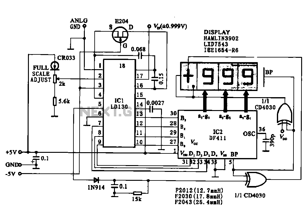
This circuit illustrates a display driving system for a digital voltmeter. The liquid crystal display (LCD) does not emit light by itself; it relies on external incident light for visibility. The integrated circuit (IC) LD130 serves as an input...
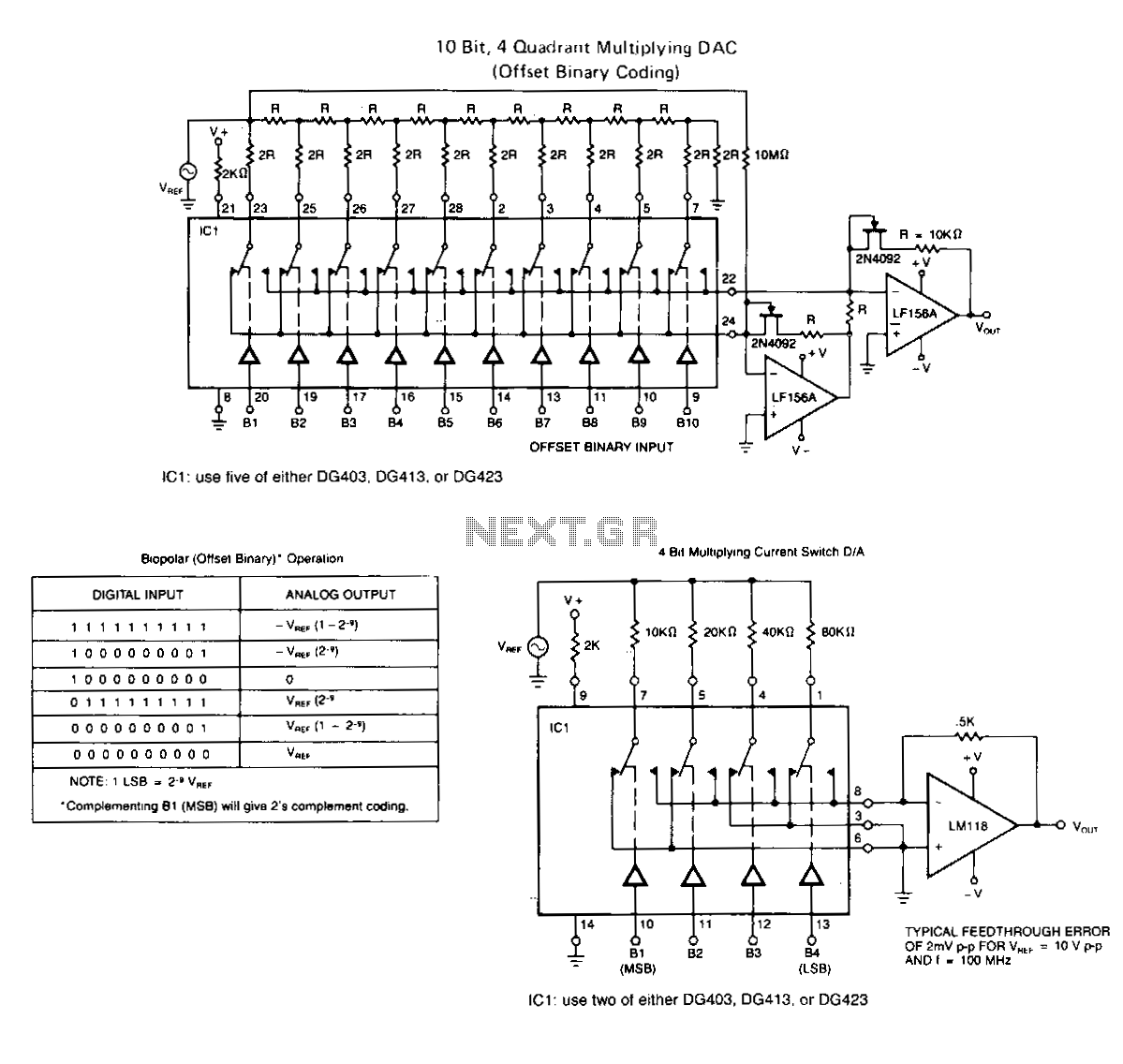
The following application circuits are intended to illustrate specific points: A 2 kΩ resistor should be placed in series with V+ to limit supply current and mitigate negative ringing of the bit inputs. Temperature compensation for Rns(on) can be...
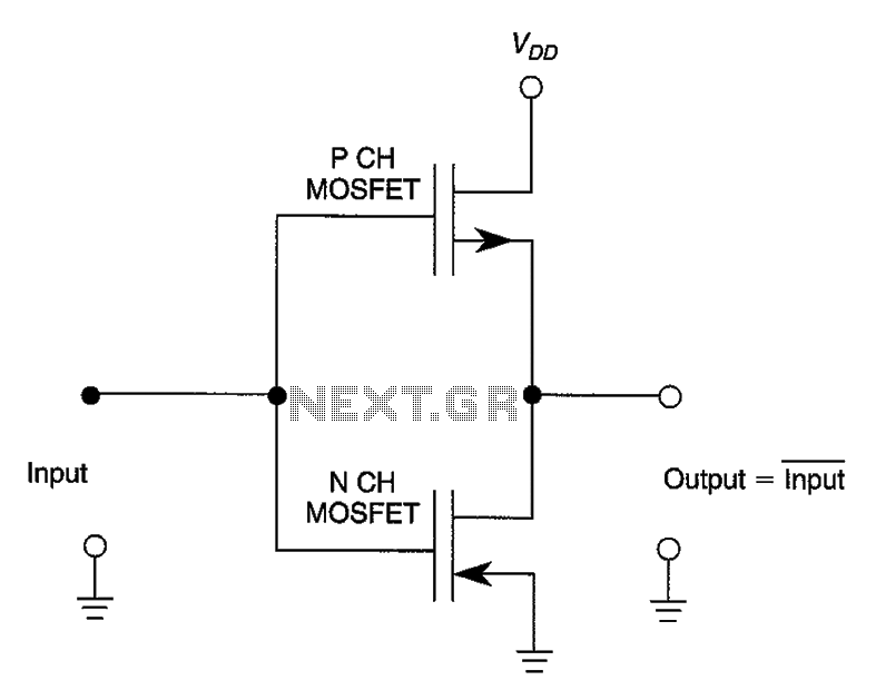
The configuration involves connecting two FETs to create a CMOS digital inverter. The CMOS (Complementary Metal-Oxide-Semiconductor) digital inverter is a fundamental building block in digital electronics, widely used in various applications such as logic gates, amplifiers, and memory circuits. This...
The operation of the converter is based on the weighted addition and transfer of the analog input levels to the digital output levels. It consists of... The converter functions by utilizing a weighted summation technique to process analog signals and...
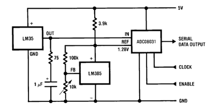
The circuit illustrates a Temperature to Digital Converter diagram utilizing the LM35 sensor, which includes a beneficial bypass capacitor connected from VIN to ground and a series RC damper. The described circuit employs the LM35 temperature sensor, a precision integrated...