
digital speedometer circuit schematic

The circuit operates by utilizing the principle of interruption of an infrared light beam. As the vehicle moves, the disc rotates synchronously with the front wheel. The infrared LED emits a continuous beam of light towards the phototransistor. When a hole in the disc aligns with the IR LED and phototransistor, the light beam is momentarily interrupted, causing the phototransistor to switch from a non-conductive to a conductive state. This transition generates a pulse that can be detected by the LM324 comparator.
The LM324 is a quad comparator IC that can compare the voltage levels at its inputs. In this application, it is configured to generate a high output signal when the voltage at the inverting input (connected to the phototransistor) falls below a certain threshold. This output is a square wave signal, and its frequency directly correlates with the rotational speed of the disc, which in turn reflects the speed of the vehicle.
To convert the frequency of the output signal into a speed reading, additional circuitry is often employed. This may include a frequency-to-voltage converter or a microcontroller that can count the pulses over a defined time period and calculate the corresponding speed in km/h. The output from the LM324 can also be used to drive a display unit, providing real-time speed information to the driver.
In summary, this vehicle speed measurement circuit effectively combines mechanical rotation with optical sensing and electronic signal processing to provide accurate speed readings, making it a valuable component in automotive applications.This circuit serves to show the speed of the vehicle in kmph. An opaque disc is mounted on the spindle attached to the front wheel of the vehicle. The disc has about equidistant holes on its periphery. On one side of the disc an infrared LED is fixed and on the opposite side of the disc, in line with the IR LED, a phototransistor is mounted. IC LM 324 is wired as a comparator. When a hole appears between the IR LED and phototransistor, the phototransistor conducts. Hence the voltage at collector of the phototransistor and inverting input of LM324 go low`, and thus output of LM324 becomes logic high`. So rotation of the speedometer cable results in a pulse (square wave) at the output of LM324. The frequency of this waveform is proportional to the speed. 🔗 External reference
Related Circuits
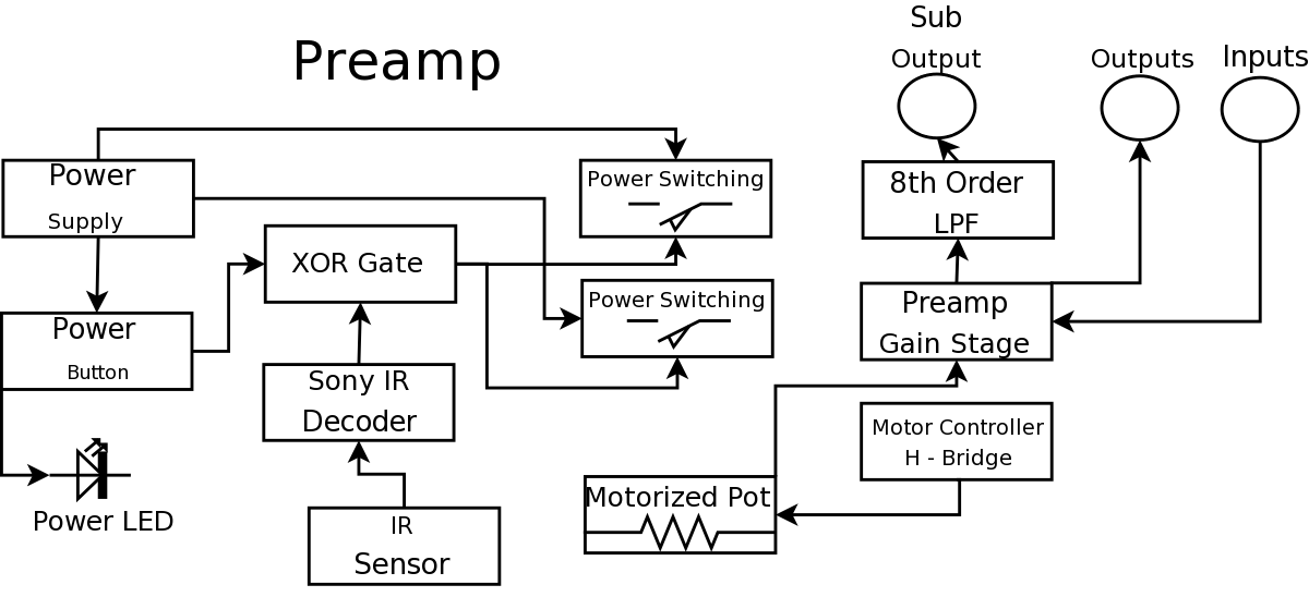
During a Digital Projects Lab, the professor suggested incorporating more circuit-level work into a project. To achieve this, a preamplifier was designed, which included an infrared (IR) remote control to replace a previously built version. The earlier preamplifier functioned...
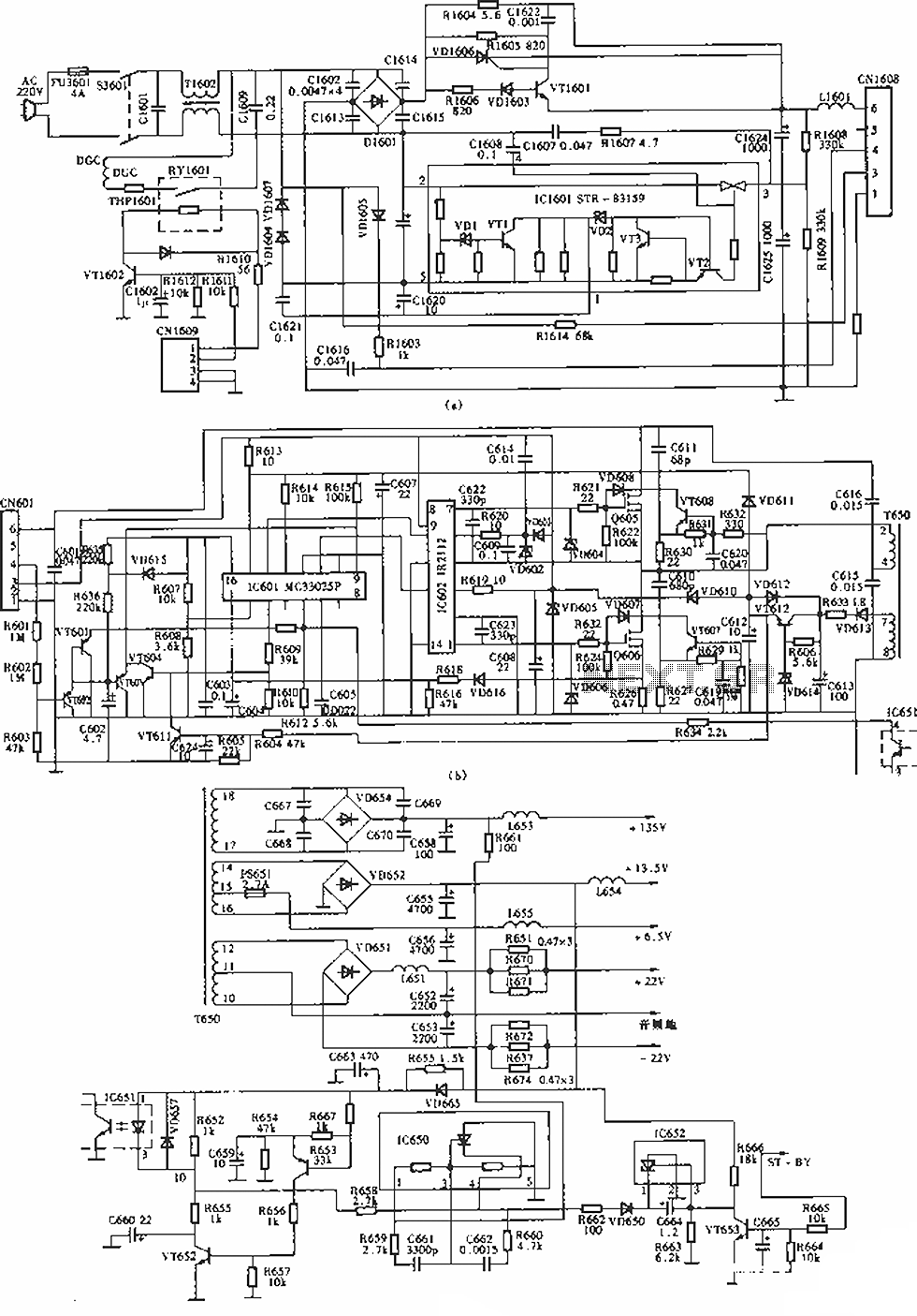
The circuit of the Sony KV-S29MHl (S Movement series) TV switching power supply (SIR a 80145A) consists of three main sections: (A) the power oscillation part, (B) the regulator part, and (C) the output section. The Sony KV-S29MHl TV switching...
This is not a sophisticated automatic keyer but it is lot QRP to build and to have fun operating it. When the paddle is connected to the DOT terminal, C1 starts to charge. When C1's charge reaches sufficiently high value,...
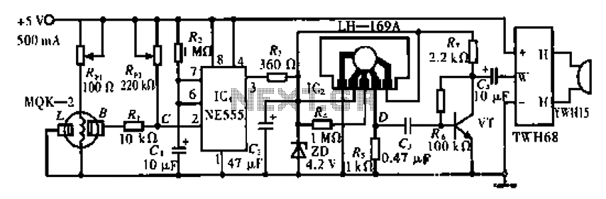
The circuit operates using the MQK-2 gas sensor, which detects the presence of combustible gases or smoke through surface adsorption. When gas is detected, the inter-electrode resistance (BL) decreases significantly. This change in resistance affects the voltage at node...

The White's Classic I was a straightforward and user-friendly metal detector, making it suitable for entry-level enthusiasts. It featured a simple design with only an on/off switch and a discriminator adjustment knob. Although it lacked depth, it was capable...
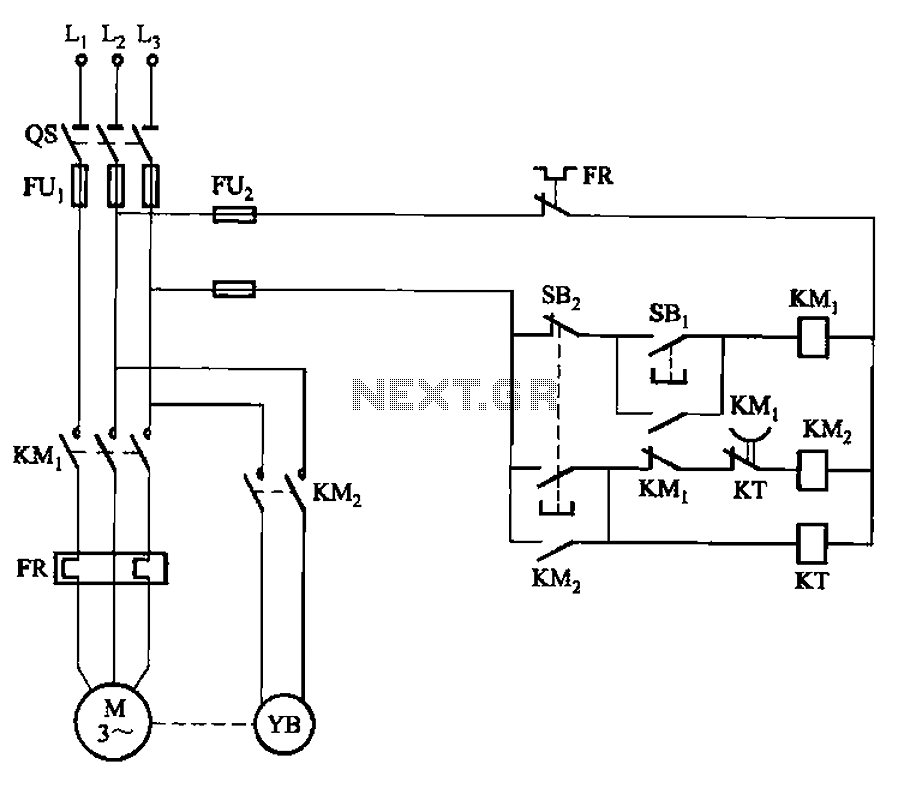
The circuit illustrated in Figure 3-123 operates as follows: When the stop button SBz is pressed, contact KMi releases, cutting off power to the motor. Simultaneously, KMz is activated, engaging the electromagnetic brake YB to hold the motor in...