
Electronics Motor Controller AC Motor

The electronics motor control circuit operates without the need for integrated circuits, making it a straightforward design suitable for basic applications. This circuit typically utilizes discrete components such as resistors, capacitors, diodes, and transistors to manage the operation of an AC motor.
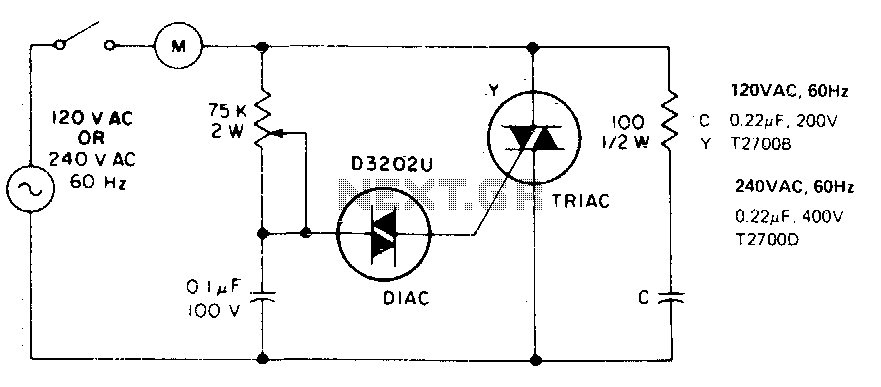
A common configuration for such a circuit includes a triac or a thyristor, which serves as the primary control element. The triac is responsible for switching the AC voltage to the motor on and off, thereby controlling its speed and direction. The gate of the triac can be triggered by a control circuit, which may include a variable resistor (potentiometer) to adjust the firing angle, allowing for speed control.
The circuit may also incorporate a zero-crossing detector to ensure that the triac is triggered at the appropriate point in the AC waveform, minimizing electrical noise and reducing stress on the motor. Additionally, snubber circuits can be included to protect the triac from voltage spikes caused by inductive loads, ensuring reliable operation.
In terms of the circuit diagram, it typically displays the connections between the AC power source, the control components, and the motor. The diagram should clearly indicate the positions of the triac, control resistors, and any protective components. Proper labeling of each component is essential for clarity and ease of understanding.
Overall, this electronics motor control circuit is a practical solution for controlling AC motors in various applications, ranging from small appliances to industrial machinery, while maintaining simplicity in design.Electronics motor control is a simple circuit made without IC.electronics control of AC motor.circuit diagram with description of electronics motor controller. 🔗 External reference
Related Circuits
This single time-constant circuit can be utilized for proportional speed control of induction motors, such as shaded pole or permanent split-capacitor motors, when the load remains constant. The circuit is particularly well-suited for applications that necessitate speed control within...
A DC drive for a universal motor is depicted in the figure below. To provide DC current to the motor, a diode bridge has been integrated around the motor. The motor... The schematic illustrates a DC drive system designed for...
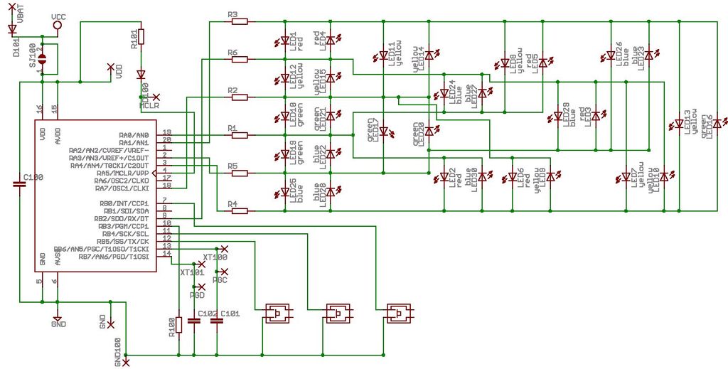
Microdot - wrist watch LED pattern timepiece. This project is a circuit board designed for creating a wristwatch-sized version. The Microdot wristwatch project involves the design and implementation of a compact circuit board that integrates LED technology to display time...
This PWM controller circuit is suitable for managing small motors with a maximum current consumption of 2A. For higher currents, additional cooling is required. The PWM (Pulse Width Modulation) controller circuit is designed to efficiently control the speed of small...

Voltage regulator ICs (78xx series) provide a steady output voltage, in contrast to a widely fluctuating input supply, when the common terminal is grounded. The 78xx series of voltage regulator integrated circuits (ICs) are widely utilized in electronic circuits to...
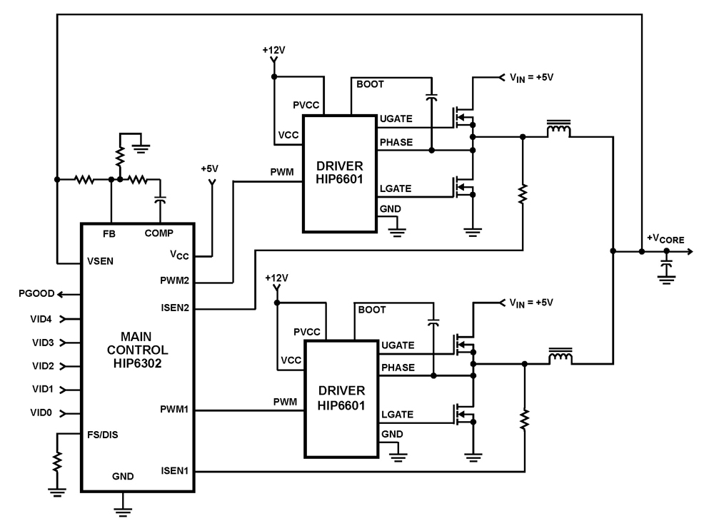
The HIP6302 Multiphase PWM control IC, along with its companion gate drivers (HIP6601, HIP6602, or HIP6603) and Intersil MOSFETs, delivers a precise voltage regulation system for advanced microprocessors. Multiphase power conversion represents a significant advancement over traditional single-phase converter...