
PWM Controller Circuit

The PWM (Pulse Width Modulation) controller circuit is designed to efficiently control the speed of small DC motors by varying the power supplied to the motor. The circuit operates by switching the power on and off at a high frequency, effectively controlling the average voltage and current delivered to the motor. This is achieved through the use of a MOSFET or transistor that acts as a switch, allowing for precise modulation of the motor's performance.
In this configuration, the PWM signal is generated by a microcontroller or a dedicated PWM IC, which determines the duty cycle of the signal. The duty cycle is the ratio of the on-time to the total period of the PWM signal, and it directly influences the speed of the motor; a higher duty cycle results in a faster motor speed, while a lower duty cycle slows the motor down.
For applications requiring current levels above 2A, it is essential to incorporate additional cooling measures, such as heat sinks or active cooling systems, to prevent overheating of the components, particularly the switching device. The circuit may also include protective features such as diodes to prevent back EMF from damaging the control circuitry when the motor is turned off.
Overall, this PWM controller circuit provides an efficient and effective means of controlling small motors, making it suitable for a variety of applications in robotics, automation, and other electronic projects.This PWM Controller circuit is ideal for controlling small motors with 2A maximum current consumption. For higher currents you need additional cooling for.. 🔗 External reference
Related Circuits
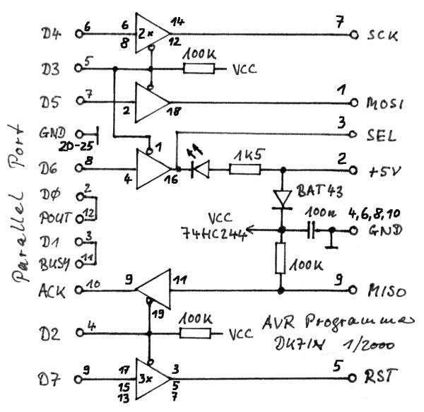
The gap between TTL (Transistor-Transistor Logic) devices and personal computers can be effectively bridged with modern microcontrollers. These microcontrollers not only incorporate a central processing unit (CPU) but also include program and data memory, EEPROM, input/output (I/O) ports, timers,...
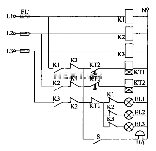
Any power supply and distribution sector should include phase sequence detection to ensure that the power supply phase sequence remains stable and unchanged. Additionally, any irreversible electromechanical product should also incorporate phase sequence detection to verify the phase sequence...
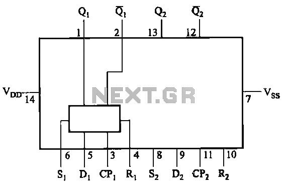
The CD4013 is a dual D flip-flop that operates on the rising edge of the clock signal. Its internal block diagram and pin configuration are provided. This device is part of the standard model C043 and the GB model...
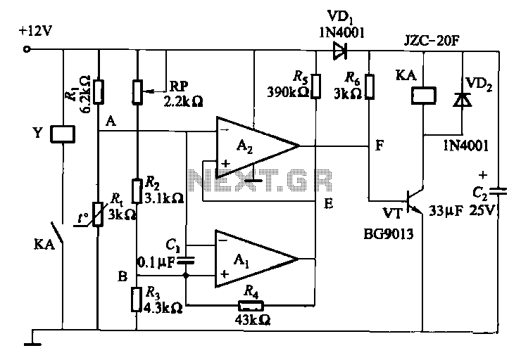
Electronic temperature control circuit for imported car air conditioners. It utilizes operational amplifiers A1 and A2, specifically the LM393 model. An adjustment potentiometer (RP) is included, allowing modification of the temperature range. The adjustment range includes a power temperature...
The digital scoreboard circuit is designed to display numerical values ranging from 0 to 9 on a common anode 7-segment display. The circuit employs a 7-segment driver integrated circuit (IC), specifically the 74LS47 or 74LS247. A 555 timer IC...
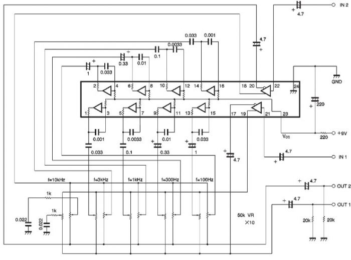
The BA3822 is a five-point stereo graphic equalizer integrated circuit that operates with two channels. Each channel can independently set five center frequencies using external capacitors. This integrated circuit supports a wide operating power supply voltage range (VCC =...