
Induction-motor control
The single time-constant circuit operates by modulating the voltage applied to the motor based on the desired speed setting. It typically consists of a resistor and capacitor in series, forming an RC time constant that influences the charging and discharging rates of the capacitor. This configuration allows for gradual adjustments in the motor's speed, providing smoother operation compared to abrupt changes.
In practical applications, the circuit can be integrated with a control mechanism, such as a potentiometer, which enables the user to set the desired speed. The output voltage is then adjusted proportionally, allowing for fine-tuning of the motor's performance. This is particularly advantageous in scenarios where maintaining a specific speed under varying load conditions is critical.
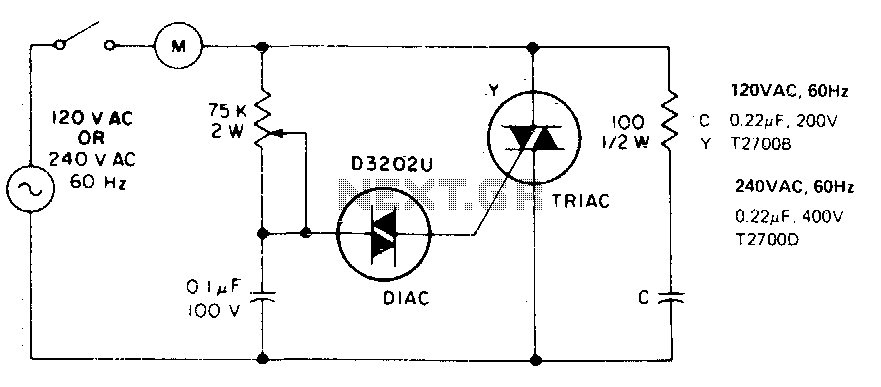
The use of this circuit is ideal for medium to full-power applications, where the motor must operate efficiently without excessive wear or overheating. By maintaining a fixed load, the circuit ensures that the motor runs optimally, providing reliable performance over extended periods. Additionally, the simplicity of the design allows for easy implementation and maintenance, making it a preferred choice for many industrial and commercial applications requiring precise speed control.This single time-constant circuit can be used as proportional speed control for induction motors such as shaded pole or permanent split-capacitor motors when the load is fixed The circuit is best suited to applications which require speed control in the medium to full-power range. 🔗 External reference
Related Circuits
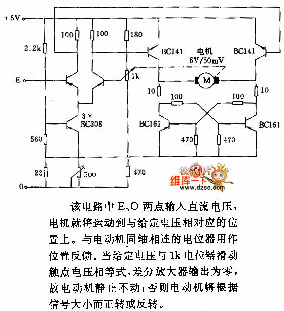
In the circuit, when E and O are input DC voltages, the motor moves to a position corresponding to the voltage. A potentiometer, coaxially connected to the motor, is used for position feedback. When the given voltage equals the...
The circuit utilizes standard components, produces a good sine wave, and exhibits a degree of immunity to the specific operational amplifier it is designed around. However, it can be easily misunderstood, and oversimplifications regarding its operation may lead designers...
This article is about a software controlled, parallel port-interfacing 8-channel Pulse-Width-Modulated fan controller. I'll admit that the electronic part of it isn't very advanced, but hopefully the idea of "interfacing" might be interesting. My old partner and I were working...
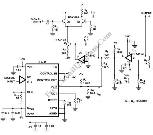
The Automatic Gain Control (AGC) is utilized in various systems, particularly in communications. This AGC operates at a frequency of 50 MHz, and the output voltage is determined by a required digital signal. The Automatic Gain Control (AGC) circuit plays...
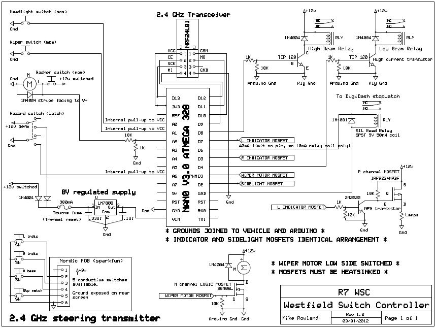
The core of the switch controller is an Arduino Nano microcontroller, which will serve as the interface between the dashboard switches, wireless steering wheel buttons, and the vehicle's lighting, indicators, windscreen wipers, and DigiDash2 GPS stopwatch. This setup facilitates...
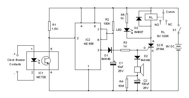
A clock-controlled relay, also known as a time delay relay, allows for the automatic activation of a load, such as a water pump, at a predetermined time. This device utilizes a standard clock mechanism to trigger the circuit, enabling...