
In-Circuit Transistor Tester
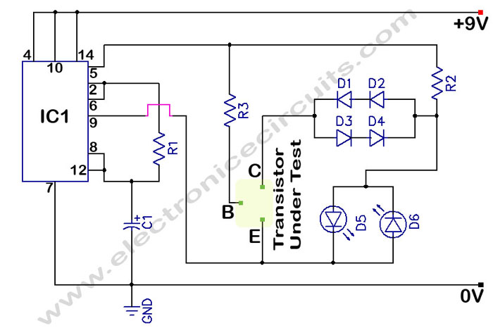
The circuit transistor tester is designed to evaluate the functionality of both NPN and PNP transistors by providing visual feedback through the use of two light-emitting diodes (LEDs). The schematic typically includes a power supply, resistors for current limiting, and a configuration that enables the user to connect the transistor under test.
For an NPN transistor, when the base is correctly biased, one LED will illuminate, indicating that the transistor is functioning properly. Conversely, if the transistor is faulty, neither LED will light up. The circuit can be enhanced by incorporating a switch to allow the user to choose between testing NPN and PNP transistors. In the case of a PNP transistor, the LED indicators will operate in a similar manner but with reversed polarity.
Key components of the circuit include:
1. **Power Supply**: Typically a low-voltage DC source, such as a 9V battery, is used to power the circuit.
2. **Resistors**: These are crucial for limiting the current through the LEDs to prevent damage. The values of these resistors are calculated based on the forward voltage of the LEDs and the supply voltage.
3. **Transistor Socket**: A socket or terminals are provided for easy insertion of the transistor being tested. This allows for quick swapping between different transistors.
4. **LEDs**: Two LEDs are used, one for indicating a good transistor and the other for indicating a bad one. The colors can be chosen for clear differentiation, such as green for good and red for bad.
Additional features may include a multimeter interface to measure the transistor's gain (hFE), or a buzzer that sounds an alert if the transistor is defective. The circuit can be compactly designed on a printed circuit board (PCB) for durability and ease of use.
This transistor tester is a valuable tool for electronics enthusiasts and professionals, providing a quick and effective means of diagnosing transistor health in various electronic projects.In Circuit Transistor Tester Schematic Here is a circuit that can indicate the condition of a transistor by using two LEDs. A good NPN transistor.. 🔗 External reference
Related Circuits
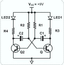
This circuit is straightforward and easy to construct, utilizing two transistors as active components along with several passive components such as resistors, capacitors, and two LEDs. The circuit employs the MPS2222 transistor, though any NPN type transistor can be...
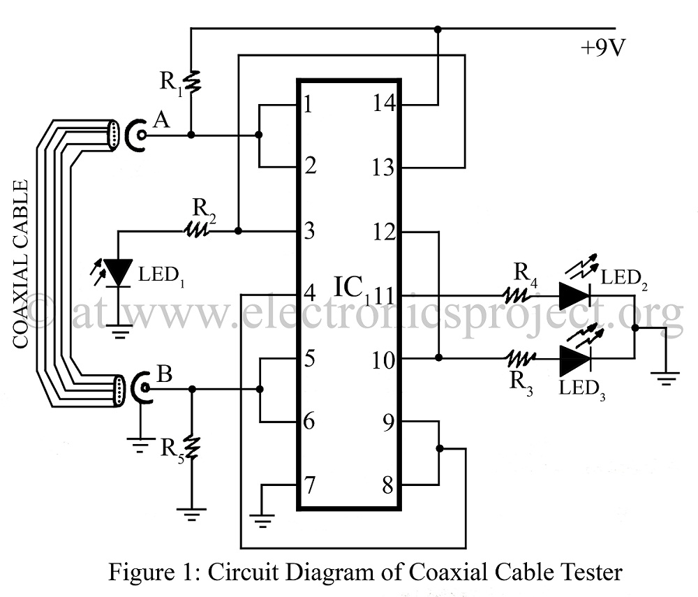
A coaxial cable tester is utilized to determine the condition of a coaxial cable, identifying whether it is open, short-circuited, or functioning correctly. This device employs a digital IC 4001 and includes a circuit description along with a parts...
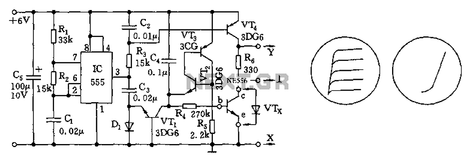
The transistor characteristic curve tracer circuit depicted in Figure 555 illustrates the characteristics of a transistor. It utilizes two voltages: a step wave applied to the base (b) to generate different base currents (Ib), and a sawtooth waveform at...
A good/bad transistor tester is an instrument designed to determine the operational status of a transistor, indicating whether it is functional or defective. This device provides a simple binary assessment, confirming if the transistor has a gain equal to...
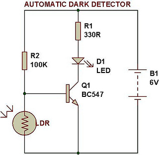
An automatic dark detector senses darkness. As the light level decreases and the light-dependent resistor (LDR) reaches the maximum threshold resistance, the circuit automatically activates the LED D1. Conversely, a light detector senses light, and when the light level...
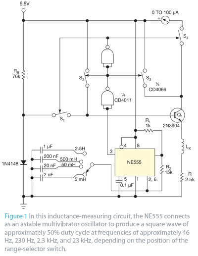
Bipolar junction transistors transfer a current from a lower-resistance emitter to a higher-resistance collector. This property can be utilized to measure inductance. Bipolar junction transistors (BJTs) are semiconductor devices that play a crucial role in electronic circuits by enabling the...