
Astable Multivibrator with 2 Transistors
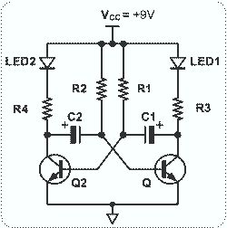
The circuit operates by leveraging the characteristics of NPN transistors, specifically the MPS2222, which is known for its reliability and efficiency in switching applications. The primary function of this circuit is to control the on/off state of the two LEDs based on the input signal applied to the base of the transistors.
In this configuration, the first transistor acts as a switch that controls the second transistor. When a sufficient voltage is applied to the base of the first transistor, it allows current to flow from the collector to the emitter, effectively turning it on. This action in turn activates the second transistor, which completes the circuit for the LEDs, causing them to illuminate.
The passive components, including resistors and capacitors, play crucial roles in determining the operating characteristics of the circuit. Resistors are used to limit the current flowing through the LEDs and to set the base current for the transistors. Capacitors can be included to filter noise or to create delays in switching, depending on the desired behavior of the circuit.
Overall, this circuit serves as a fundamental example of using transistors in a switching application, demonstrating key electronic principles such as current amplification and the control of load devices like LEDs. It is suitable for educational purposes and can be adapted for various applications in electronic projects.This circuit is basically simple and easy to build, it uses two transistors as active components and a few passive components like resistors, capacitors and two LEDs. The circuit makes use of the MPS2222 transistor. You can use any NPN type transistor as the basis of your circuit provided that, the transistors Emitter-Base Voltage is less than 12V and has a..
🔗 External reference
Related Circuits
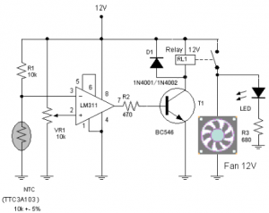
The circuit schematic diagram of a fan speed control system that activates only when necessary. When the transistor heats up, the fan will automatically turn on. The fan speed control circuit operates based on the temperature of the transistor, utilizing...
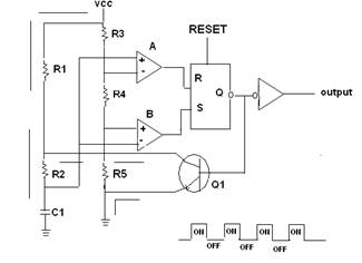
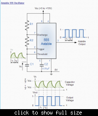
A 555 timer IC is utilized as an astable multivibrator, as illustrated in the accompanying figure (A). The threshold input is connected to the trigger input (Pin 2). The resistor R1, resistor R2, and capacitor C1 form the timing...
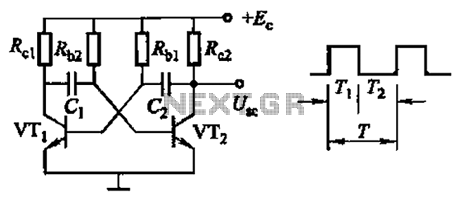
Common non-sinusoidal oscillator circuit, waveform and frequency formula - square wave oscillator - self-excited multivibrator The common non-sinusoidal oscillator circuit, specifically the square wave oscillator, is a fundamental electronic circuit utilized to generate square wave signals. It operates based on...

Control a small 5V motor using an external power supply by triggering a transistor with an Arduino. The transistor in use is an NPN type, specifically the 2N3904. To control a small 5V motor using an Arduino and an NPN...

The 555 timer integrated circuit (IC) is an exceptionally versatile component utilized in various applications, including generating clock pulses, switch debouncing, and functioning as an output transducer. The standard 555 IC is packaged in an 8-pin configuration, available in...
In the following astable multivibrator circuit, some sources state that the duty cycle is represented as d = (R1 + R2) / (R1 + 2 * R2), while other sources provide different information. The astable multivibrator circuit is a type...