
Long Range FM Transmitter
The FM transmitter circuit operates within the designated frequency band, ensuring compliance with FM broadcasting standards. The core of the circuit typically includes a voltage-controlled oscillator (VCO) that generates the desired frequency. The stability of the transmitter is enhanced by using high-quality components, such as low-noise transistors and precise capacitors, which minimize frequency drift.
To achieve harmonic suppression, the circuit may implement a band-pass filter that allows only the desired frequency to pass while attenuating unwanted harmonics. This feature is crucial for maintaining signal clarity and preventing interference with adjacent channels. The transmitter's output stage is designed to provide sufficient power to achieve the specified range of 5 km, often utilizing a class C amplifier for efficient operation.
Power supply considerations are also essential, as the circuit must maintain stable voltage levels to ensure consistent performance. Bypass capacitors are typically used to filter out noise from the power supply, further contributing to the overall stability of the transmitter.
A tuning mechanism, often in the form of a variable capacitor or an adjustable inductor, allows for fine-tuning of the output frequency, enabling the user to select any frequency within the 88 to 108 MHz range. Additionally, an antenna matching network may be included to optimize the impedance between the transmitter and the antenna, maximizing the effective radiated power.
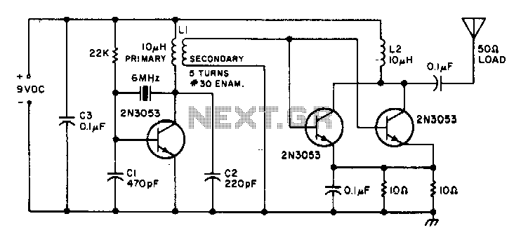
Overall, this FM transmitter circuit is suitable for various applications, including hobbyist projects, educational purposes, and small-scale broadcasting, where a reliable and stable transmission is required.This is very stable, harmonic free, long range fm transmitter circuit which can be used for fm frequencies between 88 and 108 MHz. This can cover 5km range.. 🔗 External reference
Related Circuits
This circuit enables the generation of audio musical notes that can be heard from a distance of up to 10 meters. It consists of two main components: an infrared (IR) music transmitter and an IR music receiver. The IR...
This AM radio circuit is a low-power transmitter operating in the broadcast band. Its simplicity is achieved through the use of a single-transistor amplifier stage. The AM radio transmitter circuit operates within the standard AM broadcast band, typically ranging from...
This schematic for an experimental data transmitter utilizes optical fibers and a laser diode. The transmission frequency of the free-running oscillator is approximately 3 kHz. Resistor R5 may need to be adjusted to match the specifications of the laser...
This is a small transmitter designed to fit inside a plastic Easter egg. It delivers approximately 1 W of measured RF output into a 50-ohm dummy load and does not generate any heating issues within the circuit. The crystal...
Using a Motorola MC2833 one-chip FM transmitter, a few support components, and an MPF6660 FET RF amplifier, this transmitter delivers approximately 3 W into a 50-ohm load. It is capable of operation over a frequency range of about 29...
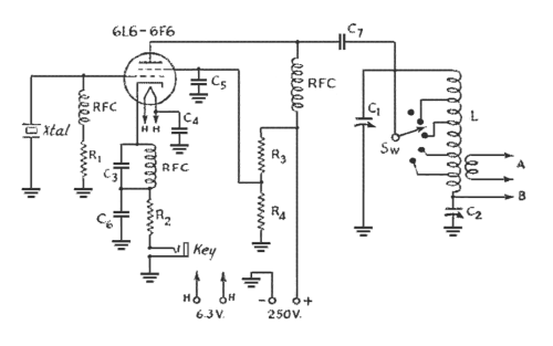
An oscillator-only transmitter appears to be the simplest way to access the radio airwaves; however, it presents several challenges as part of a transmitting and receiving station. The issue of finding an adequate crystal-controlled transmitter for newcomers wishing to...