
Small Broadcast-Band AM Transmitter
The AM radio transmitter circuit operates within the standard AM broadcast band, typically ranging from 530 kHz to 1700 kHz. The core of the circuit is a single-transistor amplifier, which serves to modulate the audio signal onto the carrier frequency.
The circuit begins with an audio input, which could be sourced from a microphone or an audio playback device. This audio signal is then fed into the base of the transistor, which functions as a modulator. The transistor is configured in a common emitter mode, providing both amplification and phase inversion of the input signal.
A key component of the circuit is the LC tank circuit, which consists of an inductor and a capacitor. This tank circuit is essential for determining the frequency of the transmitted signal. The values of the inductor and capacitor must be carefully selected to resonate at the desired frequency within the AM band.
The output of the transistor is connected to an antenna, which radiates the modulated signal into the surrounding environment. The efficiency of the antenna can significantly affect the transmission range of the circuit. A simple wire antenna can be used, but its length should be approximately one-quarter of the wavelength of the desired transmission frequency for optimal performance.
Power supply requirements for this low-power transmitter are minimal, often operating from a standard battery or low-voltage power source. Proper biasing of the transistor is crucial for ensuring linear amplification and preventing distortion of the audio signal.
Overall, this AM radio transmitter circuit exemplifies a straightforward yet effective design for broadcasting audio signals, suitable for educational purposes or hobbyist projects. The use of a single-transistor amplifier simplifies construction while still achieving functional performance within the AM broadcast band.This AM radio circuit is a low power transmitter working on broadcast band. The simplicity is implemented using a single-transistor amplifier stage, and for.. 🔗 External reference
Related Circuits
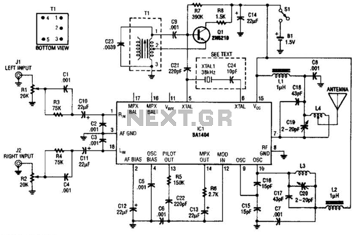
In this application, a BA1404 is utilized to generate an FM MPX baseband signal. This signal modulates a crystal oscillator (Q3) through a dual varactor series modulator. This transmitter can be used to play CD audio on an existing...
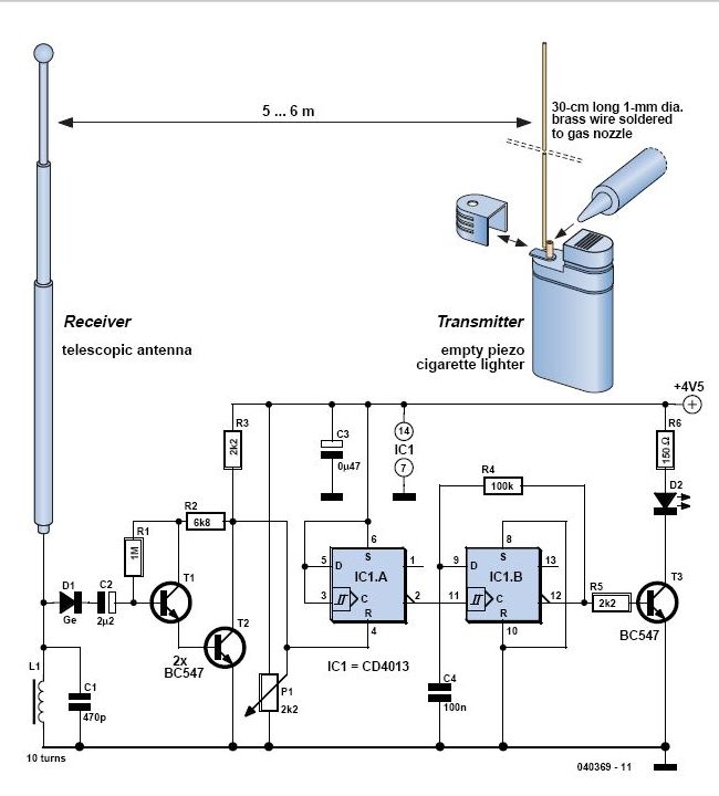
This circuit allows for the construction of a compact tracking transmitter that can be detected using an FM broadcast band radio receiver. The transmitter operates on a power source of any 1.5V battery or power supply. It has a...
This circuit is designed for low power operation and can be tuned to function within the frequency range of 87-108 MHz, achieving a transmission distance of 20 to 30 meters. The circuit utilizes a pair of BC548 transistors, which,...
.jpg)
Charging a small NiMH battery has led to the development of an innovative method for harvesting energy from the environment. This energy can be utilized for various applications, such as charging a small 9V NiMH battery or generating high...
In 1896, Marconi successfully transmitted electromagnetic waves over a distance of approximately 3 kilometers. Shortly thereafter, he established radio communication across water between Lavernock Point in South Wales and Flat Holm Island. The transmitter utilized a spark inductor connected...
Before starting on the receiver side of the Chatterbox, a final review of the transmitter is necessary. The Chatterbox transmitter is constructed separately, as many builders may wish to use it alongside an existing receiver operating at 1.8 MHz....
Warning: include(partials/cookie-banner.php): Failed to open stream: Permission denied in /var/www/html/nextgr/view-circuit.php on line 713
Warning: include(): Failed opening 'partials/cookie-banner.php' for inclusion (include_path='.:/usr/share/php') in /var/www/html/nextgr/view-circuit.php on line 713