
EXPERIMENTAL DATA TRANSMITTER FORFIBER OPTICS
The experimental data transmitter circuit is designed to facilitate the transmission of data through optical fibers using a laser diode as the light source. The CD4093 integrated circuit, which consists of four NAND gates, is employed to generate the necessary square wave signal that drives the laser diode. This IC is known for its versatility and ability to operate at low power, making it suitable for various applications in optical communication systems.
The oscillator circuit is configured to operate at a frequency of approximately 3 kHz, which is suitable for certain types of data transmission. The frequency can be fine-tuned by adjusting resistor R5, which is part of the timing network. This adjustment is crucial as it ensures that the modulation frequency aligns with the characteristics of the laser diode being used, optimizing the performance of the transmitter.
The optical fiber used in this setup serves as a medium for transmitting the modulated light signal generated by the laser diode. The choice of optical fiber should be compatible with the wavelength of the laser diode to ensure minimal signal loss and optimal data integrity. The circuit is designed to be compact and efficient, allowing for easy integration into various experimental setups where data transmission is required.
Overall, this schematic provides a foundational approach to building a basic optical data transmitter, suitable for experimentation and further development in optical communication technologies.This schematic for an experimental data transmitter uses optical fibers and a laser diode. Trans-mission frequency of the free-running oscillator is approximately 3 kHz. R5 might have to be varied to suit your laser diode. IC1 is a CD4093.. 🔗 External reference
Related Circuits
1-Transistor FM Transmitter. R1 27k, R2 56k, R3 12k, R4 100, C1 1u, C2, C3 470p, C4 6 to 10p, C5 1-30p trimmer, L1 etched on PCB. The 1-transistor FM transmitter is a compact electronic circuit designed to transmit audio...
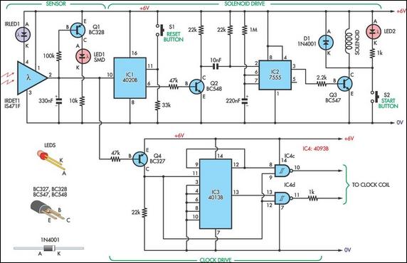
This design allows for the construction of an electromagnetically impulsed pendulum clock with a 1-second beat. The prototype features a pendulum rod measuring 115 cm in length, with a bob adjusted to achieve a 1-second beat. The pendulum is...
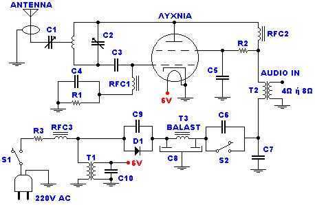
The catering better it does not become at straight line from the network 220V but via transformer 220V/220V of isolation and safety 1A. When does not exist the R3, the force of expense is bigger, but respectively is increased...
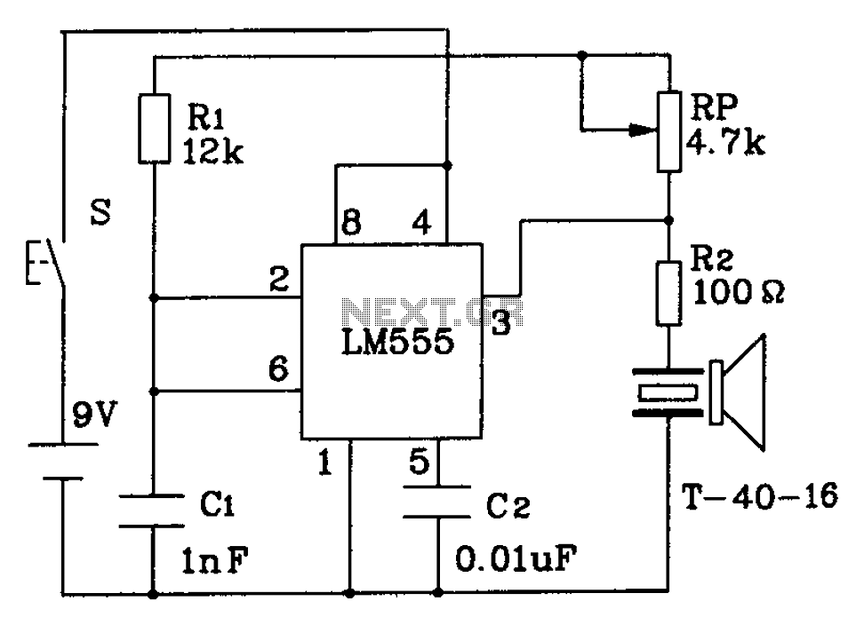
The circuit described is a 555 ultrasonic transmitter constructed to emit ultrasonic signals at a frequency of 40 kHz. It operates by generating oscillating pulse outputs from a 555 timer (specifically the T-40-16 model). The circuit is designed to...
This schematic represents an FM transmitter capable of delivering an output power ranging from 3 to 3.5 watts, operational within the frequency band of 90 to 110 MHz. While the circuit exhibits reasonable stability, a Phase-Locked Loop (PLL) can...
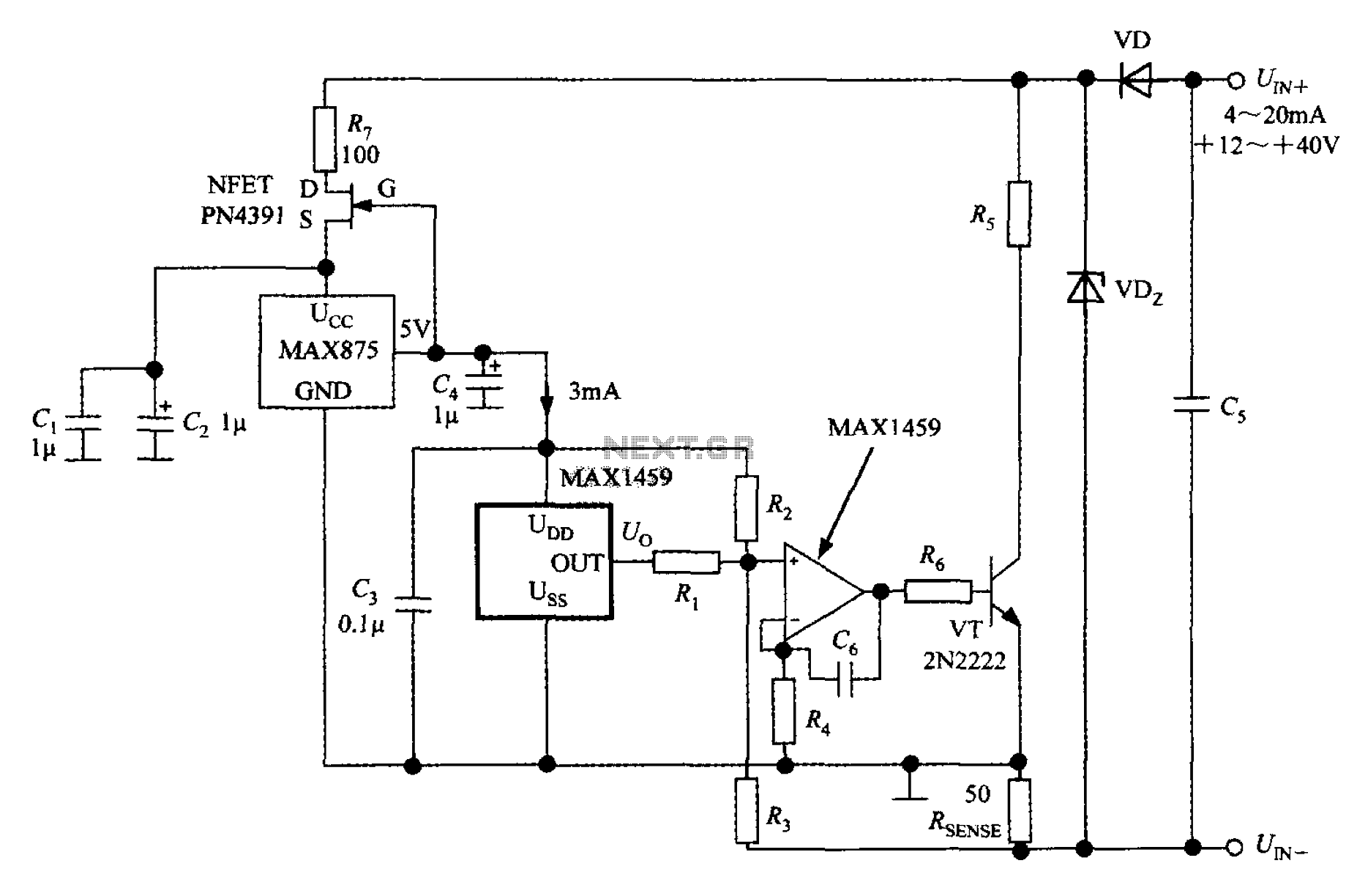
A 4 to 20 mA current transmitter circuit is implemented using the MAX1459, as illustrated in the accompanying figure. The output voltage from the programmable gain amplifier (PGA) is supplied to a spare amplifier chip, and subsequently, an external...
Warning: include(partials/cookie-banner.php): Failed to open stream: Permission denied in /var/www/html/nextgr/view-circuit.php on line 713
Warning: include(): Failed opening 'partials/cookie-banner.php' for inclusion (include_path='.:/usr/share/php') in /var/www/html/nextgr/view-circuit.php on line 713