
Long-range FM radio transmitter circuit
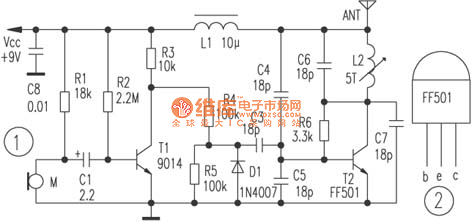
The described circuit functions as a basic RF transmitter capable of modulating audio signals for wireless transmission. The electret microphone serves as the primary audio input, converting sound waves into electrical signals. The role of transistor T1 is critical as it amplifies these signals, ensuring that the modulation process can effectively alter the carrier wave produced by the oscillator circuit formed around tube T2.
The high-frequency oscillator is essential for generating the RF signal within the specified FM broadcast band. The choice of the FF501 tube is notable for its reliability and performance in RF applications, making it suitable for this type of circuit. The TO-92 package allows for easy integration into various circuit designs while maintaining a compact form factor.
When the microphone is not in use, the circuit can seamlessly switch to a cassette player input, broadening its functionality to include music transmission. This versatility is advantageous for applications such as personal FM transmitters or small-scale broadcasting setups.
The circuit's design emphasizes adjustability, allowing the user to fine-tune the output frequency and modulation characteristics to optimize performance. The output power of the RF signal is also a crucial consideration, as it determines the effective transmission range. By leveraging the properties of the FF501 tube, the circuit can achieve a robust output suitable for various transmission needs.
Overall, this RF transmitter circuit exemplifies a straightforward yet effective design for audio transmission, combining essential components to achieve reliable performance in the FM frequency range.In the circuit shown, the special launch tube T2 and its peripheral parts form a high-frequency oscillator with frequency in the range of 88 ~ 108MHz. The electret microphone picks up the audio signal, then the signal is amplified by T1, then the amplified low frequency signal makes modulation for high-frequency carrier.
If the electret microphone M disconnects, the input end connects cassette player, and it can transmit music. The RF transmitter dedicated tube T2 chooses FF501 which uses a standard T0-92 package (like the 9000 series of transistors ), shape, and pin arrangement is shown in Figure 2. The dedicated tube has the advantages of good consistency, the RF output power is greater, and the circuit is easy to adjust, and the FF501 also can work at a higher frequency band.
🔗 External reference
Related Circuits
A small Medium Wave antenna from a walkman with digital radio and a variable capacitor (VC) with two sections connected in parallel from an old Russian radio (2x280pF). It has been noted that in areas with strong signals, optimal...

LMD18245 bipolar stepper motor driver circuit design using few electronic parts The LMD18245 is a versatile bipolar stepper motor driver designed to control stepper motors with precision and efficiency. This circuit utilizes a minimal number of electronic components, making it...

This design outlines a fire alarm circuit that utilizes a light-dependent resistor (LDR) and a lamp to detect fire. The alarm is activated by sensing the smoke produced during a fire. When smoke is present, it obstructs light from...

A gas sensor (from Allegro Electronics, Cornwall Bridge, CT06754 Ts GS823) activates in the presence of explosive gas. U5 functions as a voltage-to-frequency converter, with the sensor producing a frequency that is proportional to conductance. The output frequency varies...
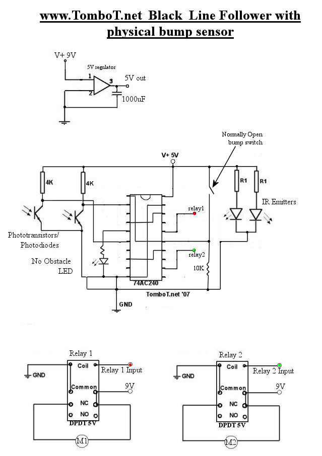
The motors will be powered by the full source voltage, so it is important to ensure that this does not cause the robot to operate too quickly. The Firebot utilizes GM3 motors powered by a 9V battery; however, in...
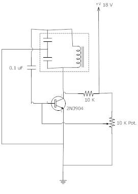
The frequency remains stable as the voltage decreases. It is referred to as the "backwards JT" because it operates optimally with a bifilar coil and a single transistor. With a modification to the circuit, it is possible to deplete...