
Seven-7-Segment Counter Circuit with LED Display-Diagram and Schematic
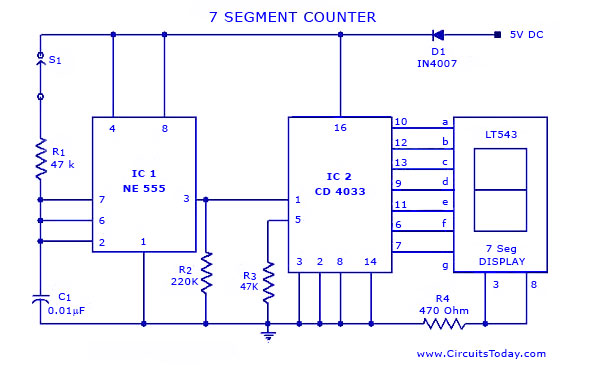
The seven-segment counter circuit utilizes the CD 4033 integrated circuit, which is a BCD (Binary-Coded Decimal) counter. This IC is capable of counting from 0 to 9 and can directly drive a seven-segment display, converting the binary output into a human-readable decimal format. The 555 Timer IC is configured in astable mode to generate a continuous clock pulse, which drives the counting process.
The circuit begins with the 555 Timer, where resistors and capacitors are chosen to set the desired frequency of oscillation. The output of the 555 Timer provides a square wave signal that serves as the clock input for the CD 4033. The frequency of this clock signal determines the speed at which the counter increments.
The CD 4033 has several pins dedicated to output, which correspond to the decimal digits. When the clock pulse is received, the counter increments its count by one with each pulse. The output pins of the CD 4033 are connected to the inputs of the seven-segment display (LT 543), which lights up the appropriate segments to represent the current count visually.
To ensure proper operation, the circuit may include additional components such as pull-up resistors or decoupling capacitors to stabilize the power supply and prevent noise from affecting the performance. The design allows for straightforward implementation and is suitable for educational purposes or as a simple counting device in various applications.A simple seven/7 segment counter circuit with an LED display. This counter circuit diagram is designed using IC CD 4033 as counter,555 Timer IC and seven segment LED Display LT 543.. 🔗 External reference
Related Circuits
This circuit is similar to the previous one but employs positive feedback to enhance the amplitude delivered to the speaker. It was adapted from a small five-transistor radio that utilizes a 25-ohm speaker. In the prior circuit, the load...
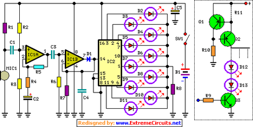
The basic circuit illuminates up to ten LEDs in sequence, following the rhythm of music or speech picked up by a small microphone. The expanded version can drive up to ten strips, each formed by up to five LEDs,...
The Lorenz system is one of the few standard oscillators commonly used to explore chaos. An accessible description of its mathematical features and chaotic dynamics is presented by Thompson and Stewart. This important system was originally developed as a...
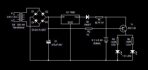
This is a high-efficiency emergency lamp that utilizes high-brightness white LEDs. It automatically activates during power failures and deactivates when power is restored. The emergency lamp circuit is designed to provide reliable illumination during power outages, utilizing high-brightness white LEDs...
WB5LUA described GaAsFET preamplifiers for several microwave bands, which included an active bias circuit for the GaAsFET. Although newer devices have been introduced that offer improved performance, they require different bias points with varying currents and voltages. Modifying the...
This site addresses a range of subjects pertaining to circuits and electronics. Some of the topics discussed on this site include: * Alternating Relay Switch * Photoswitch Relay. The site serves as a comprehensive resource for understanding various electronic components...