
Understanding the WB5LUA GaAsFET Bias circuit
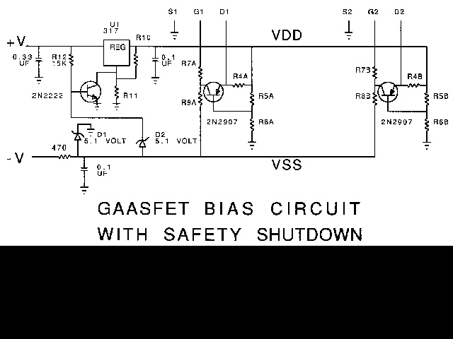
The active bias circuit for GaAsFET and PHEMT amplifiers is designed to optimize performance across various operational conditions. The two-stage amplifier configuration allows for independent control of biasing in each stage, which is critical for maintaining consistent gain and minimizing distortion. The choice of the 2N2907 transistor is significant due to its reliable performance characteristics, including low noise and high gain, making it suitable for RF applications.
The resistors R4, R5, and R6 play pivotal roles in determining the operational parameters of the amplifier. R4 is primarily responsible for setting the drain current, while R5 and R6 establish the drain voltage, which is crucial for maintaining the linearity of the amplifier's response. The feedback mechanism provided by the 2N2907 transistor ensures that any variations in voltage or current are corrected dynamically, thereby stabilizing the amplifier's performance.
The importance of a well-regulated VDD cannot be overstated, as fluctuations in this voltage can lead to significant performance degradation or even damage to sensitive components. The use of a three-terminal regulator, such as the LM317, allows for flexible voltage regulation, accommodating different types of devices and their specific requirements.
In applications with stringent noise figure requirements, careful selection of bias points based on manufacturer specifications is essential. The ability to adjust resistor values with standard components ensures that the circuit can be tailored to meet the needs of various devices, enhancing the versatility of the design. The inclusion of a spreadsheet for calculations simplifies the process of finding optimal resistor values, making it accessible for engineers and hobbyists alike.
In summary, the active bias circuit for GaAsFET and PHEMT amplifiers provides a robust solution for achieving stable and reliable performance across a range of applications. Its design principles can be adapted for various configurations, ensuring that users can effectively implement this technology in their projects, whether for low-noise preamplifiers or high-power amplifiers.WB5LUA described GaAsFET preamps for several microwave bands which included an active bias circuit for the GaAsFET. Many devices have come along since then which offer better performance, but require a bias point with different current and voltages.
It isn`t obvious how to modify the active bias circuit for a different bias point, so many folks simply resort to a potentiometer, which usually works but may drift or fail completely. Since I`ve never seen a desciption of how the active bias circuit works, I worked it out - it`s actually pretty clever. I`ll try to describe the operation so that others can utilize this circuit, not only for GaAsFET preamps, but also PHEMT preamps and GaAsFET power amplifiers.
All component references will refer to this schematic. Since it is for a two-stage amplifier, there are two active bias circuits, each with a 2N2907 transistor and five resistors, R4 thru R8, which set the bias point of each stage independently. Everything in the bias circuit is referenced to the input voltage VDD, so it is important that this is a well-regulated voltage.
Normally this is provided by a three-terminal regulator, U1, which can be a 78L05 to provide 5 volts for a normal low-noise GaAsFET, or an LM317 for other voltages. The input voltages, VDD and VSS, MUST be less than the maximum voltage rating for the GaAsFET or PHEMT or you risk burnout of an expensive device.
Some of the newer PHEMT devices with very low NF have a 3 volt maximum rating, so VDD must be regulated at 3 volts or less by an LM317, and VSS limited to 3 volts or less by an appropriate zener diode. Zeners may be hard to find for this low voltage, but a string of four forward-biased diodes in series would work fine; readily available 1N914 or 1N4148 diodes are fine.
Next we must determine the desired bias point. A good starting point is the data sheet NF specification, which usually includes the operating voltage and current for NF measurement. For instance, an MGF-1302 is measured at 3 volts and 10 ma. The bias point is set by the resistors in the bias circuit: R4 sets the drain current, while R5 and R6 determine the drain voltage.
The 2N2907 transistor (or almost any small PNP transistor) acts as a feedback amplifier which adjusts the gate voltage to maintain the desired drain voltage and current as determined by R4, R5, and R6. Values for these three resistors to set a particular Vdrain and Idrain may be calculated as follows: The easiest way to solve the second equation is to plug in an arbitrary value for R6, say 1K ohms, and solve for R5.
Then we may change the values of R5 and R6 so that they are both standard values as long as the ratio of R5 to R6 does not change, and adequate current, perhaps one milliamp, flows through R5 and R6. (Note: 0. 65 is the approximate emitter-base voltage for the 2N2907). The gate current in a preamp should be zero, so R7 and R8 may be large; 10K is a convenient value. Power amplifiers may draw gate current, and amplifiers with a stabilizing resistor from gate to ground also require current.
In these cases, R7 and R8 should be significantly smaller so that this current does not upset the gate bias. These calculations can get tedious, particularly trying to find standard resistor values. To make it easier, I made up a small Excel spreadsheet to do the calculations (hold down the shift key while clicking here to download ), and entered three different examples as starting points: a GaAsFET preamp, a PHEMT preamp, and a GaAsFET power amp.
With the spreadsheet, it is easy to fiddle things for the desired bias point with standard or available resistor values. A small adjustment in VDD is useful in adjusting R4, so R10 and R11 are included for setting VDD by changing R11.
Use of an active bias circuit GaAsFET (or IMFET) power amplifiers can help stabilize operation and prevent disasters. Operation is the same as for preamps, but voltage and 🔗 External reference
Related Circuits
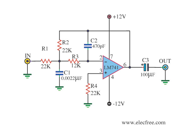
This circuit filters low frequencies below 10 kHz using the highly popular operational amplifier IC uA741. It is convenient for applications that require the conversion of analog signals to digital or vice versa. In digital sound systems, this circuit...

A Field Effect Transistor (FET) is an amplifying device where the output current is influenced by the input voltage. The FET preamplifier described here is sensitive. The Field Effect Transistor (FET) operates by utilizing an electric field to control the...
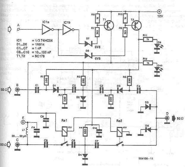
This antenna selector circuit diagram electronic project is constructed using standard electronic components and facilitates the switching between two FM antennas through a logic signal. The gates IC1b and IC1a manage the switching and interface between the required logic...
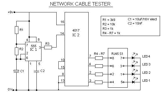
This is a multifunction RJ45 network cable tester designed for testing network cables (RJ45) and telephone cables (RJ11). It is cost-effective and user-friendly. The tester determines whether a network cable is a crossover or straight type by illuminating a...
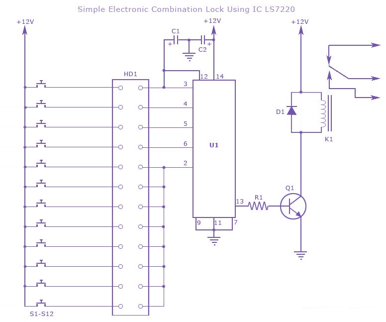
A simple electronic combination lock using the IC LS7220. This circuit employs a relay to control any device when a combination of four digits is entered. Keypads serve as the input method for entering the digits, and the correct...
This presence detector or proximity sensor circuit responds to the presence of any conductive object, including humans. The sensitivity can be adjusted with potentiometer P1, which is positioned at a considerable distance from the rest of the circuit. This...