
Step up Voltage converter DC to DC
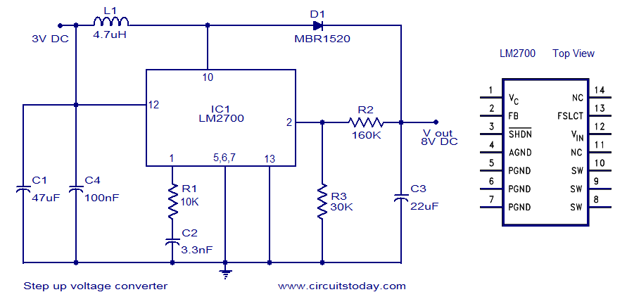
The LM2700 is a versatile step-up switching converter designed to efficiently convert a lower input voltage to a higher output voltage. This circuit is particularly useful in applications where the supply voltage is insufficient for the required load, such as powering portable devices from a single-cell battery.
The schematic typically includes several key components: the LM2700 integrated circuit, input and output capacitors, an inductor, a diode, and feedback resistors. The input voltage is applied to the LM2700, which controls the switching of the internal transistor. The inductor stores energy during the 'on' phase and releases it to the output during the 'off' phase, effectively increasing the voltage.
The output voltage can be adjusted by selecting appropriate values for the feedback resistors, allowing for a range of output voltages to be achieved based on the application requirements. The output capacitor smooths the output voltage, providing a stable power supply to the load.
The circuit should also include necessary protection features, such as input and output capacitors to filter noise, and possibly a thermal shutdown feature to protect against overheating. Proper layout and component selection are critical to minimize losses and ensure stable operation across varying load conditions.
In summary, the LM2700-based step-up converter circuit is an efficient solution for applications requiring a higher voltage from a lower input, with flexibility in output voltage settings and essential protective components for reliable performance.A simple dc to dc step up voltage converter circuit schematic using LM2700-which is a step up switching converter.. 🔗 External reference
Related Circuits
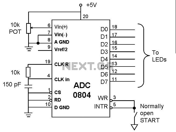
This post discusses the interfacing and operation of Analog-to-Digital Converters (ADCs). An ADC is a device that converts the analog signals from transducers into digital signals, enabling computers to process the data. ADCs are essential for obtaining meaningful results...
The circuit diagram was designed to create a power supply without utilizing any transformer circuit. This circuit illustrates the advantages as well as the limitations of transformerless power supplies. The transformerless power supply circuit typically employs a capacitive dropper method...
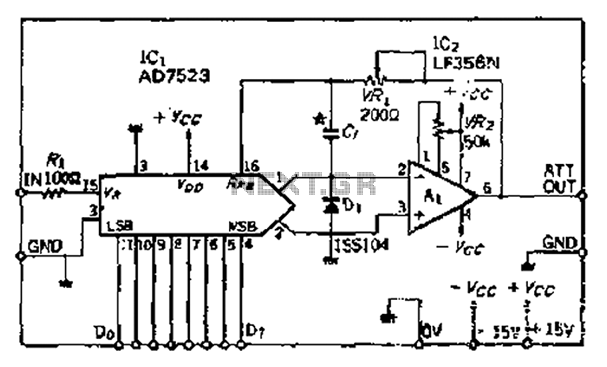
The AD7s23 is an 8-bit multiplying digital-to-analog (DA) converter that generates an output voltage based on both the analog and digital inputs. The unit comprises eight analog switches and utilizes a ladder network configuration. This ladder serves as a...
Binary Coded Decimal (BCD) is a number system that counts from 0 to 9 and then repeats. The table below illustrates the conversion between different numbering systems and BCD code. BCD is also known as 8421 because the least...
Before World War II the FM radio band was just below 50 Mc. Read all about it. If you have such a radio, you might want to build this converter. It will let your old set receive the modern...
Low-pass and high-pass audio output signal filters are included. An additional sound source low-pass filter and an experimental original design pulse-gate signal filter ("processor") are available, both featuring independent or linked voltage control input options. The synthesizer can function...