
Low Voltage Power Supply Without Transformer

The transformerless power supply circuit typically employs a capacitive dropper method or a resistive dropper method to convert AC mains voltage to a lower DC voltage suitable for powering low-power electronic devices. The absence of a transformer reduces the overall size and cost of the circuit, making it an attractive option for compact applications.
In a capacitive dropper circuit, a non-polarized capacitor is placed in series with the AC supply. This capacitor limits the current flowing into the load, allowing for a reduced voltage across the output. The output is then rectified using a diode and smoothed with a capacitor to provide a stable DC voltage. It is essential to select the capacitor value carefully to ensure that the output current remains within safe limits for the intended application.
Alternatively, a resistive dropper circuit uses a resistor in series with the load to limit the current. While this method is simpler, it is less efficient than the capacitive method, as it dissipates power as heat. The output voltage is again rectified and filtered to provide the desired DC output.
Both methods have their advantages and disadvantages. Transformerless power supplies are lightweight and cost-effective but may lack the isolation provided by traditional transformer-based power supplies. They also pose safety risks, as the output is directly connected to the mains voltage, necessitating careful design to ensure user safety.
In summary, transformerless power supply circuits are suitable for low-power applications where size and cost are critical factors, but they require careful consideration of safety and performance parameters.The circuit diagram was designed to create a power supply without utilizing any transformer circuit. This circuit illustrates the advantages as well as th.. 🔗 External reference
Related Circuits
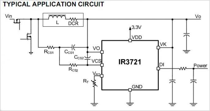
The International Rectifier IRAM109-015SD is a multi-chip hybrid integrated circuit designed specifically for low-power appliance motor control applications, including fans, pumps, and refrigerator compressors. Its compact single in-line package (SIP-S) optimizes PCB space. The device includes several built-in protection...
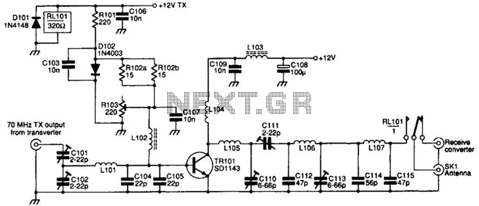
The SD1143 transistor offers a gain of approximately 14 dB in this circuit. Its design takes advantage of the fact that a 175-MHz device exhibits significantly higher gain when operated at lower frequencies. The amplifier was initially intended for...
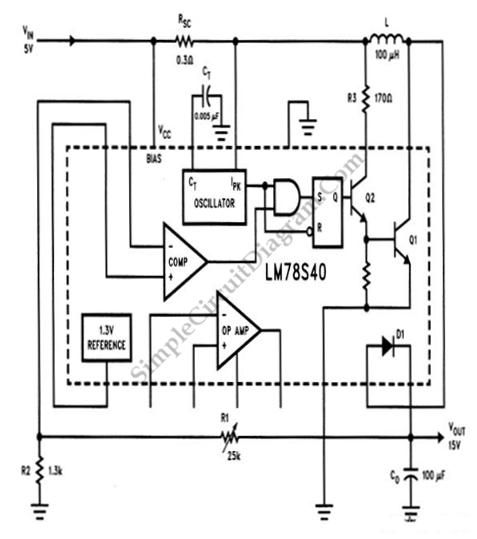
A step-up conversion can be achieved without utilizing a transformer. This circuit is capable of converting a 5V DC source into 15V. It is important to note that there is no power gain. The described circuit employs a DC-DC boost...
The range of this FM transmitter is approximately 100 meters when powered by a 9V DC supply. The circuit consists of three stages. The first stage is a microphone preamplifier. The FM transmitter circuit is designed to convert audio signals...
The two circuits demonstrate the process of opening a relay contact shortly after the ignition or light switch is turned off. The capacitor is charged, and the relay remains closed until the voltage at the diode anode reaches +12...
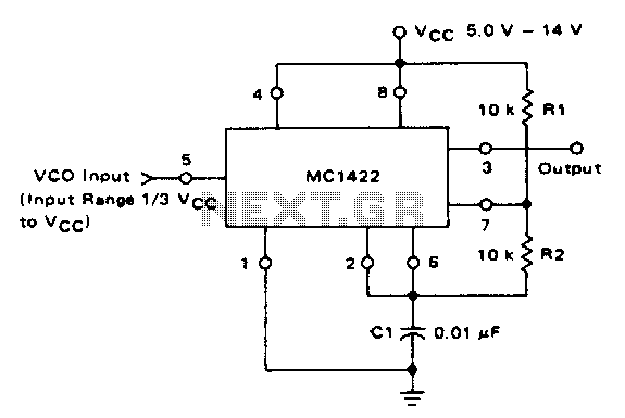
The VCO circuit, which has a nonlinear transfer characteristic, will operate satisfactorily up to 200 kHz. The VCO input range is effective from V% Vcc to Vcc - 2 V, with the highest control voltage producing the lowest output...