
The Colpitts oscillator
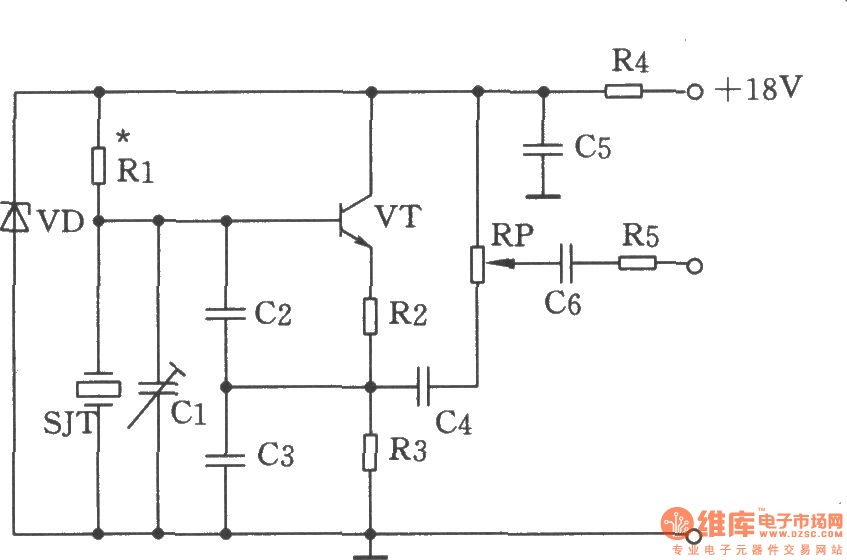
The Colpitts oscillator is a type of LC oscillator that generates sine wave signals at a specific frequency determined by the values of its inductors and capacitors. In this circuit, the crystal SJT acts as a frequency-determining element, ensuring stability and precision in the output frequency of 1499 kHz. The capacitors C2 and C3 form a capacitive voltage divider that influences the feedback voltage fed back to the base of the transistor, which is essential for maintaining oscillation.
The resistors R2 and R3 serve as part of the emitter feedback network. They create a voltage divider that provides a portion of the output signal back to the input, which is crucial for sustaining oscillation. The interaction between the capacitors and the resistors enables fine-tuning of the feedback level, thereby stabilizing the oscillation amplitude.
The output of the Colpitts oscillator is a sine wave signal, which can be accessed at the collector of the transistor. This output can be utilized in various applications, including signal generation, clock pulses for digital circuits, and as a local oscillator in radio frequency (RF) applications. The design parameters, such as the values of the capacitors and resistors, can be adjusted to achieve the desired frequency and output characteristics, making the Colpitts oscillator a versatile choice for frequency generation in electronic circuits.Figure shows the Colpitts oscillator circuit. It has a base frequency crystal, and the frequency is 1499 kHz, crystal SJT is connected to the both ends of capacitor C2, C3. Emitter divider resistor R2, R3 provide basic feedback signal, the feedback voltage is controlled by the capacitive dividers C2, C3.
SJT crystal provides l499kHz sine wave signal for the.. 🔗 External reference
Related Circuits
This generally results in a square wave if the frequency of oscillation is low enough relative to the amplifier's bandwidth. The schematic of a crystal-controlled oscillator features a low-frequency sine wave oscillator characterized by low distortion, wideband operation, and...
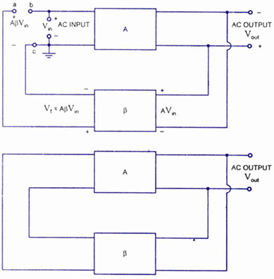
A feedback amplifier with a closed-loop gain, Af, greater than unity can be achieved through the use of positive feedback. This condition also fulfills the phase requirement, leading to the operation of an oscillator circuit. An oscillator circuit generates...

The Hartley Oscillator is an LC oscillator that derives its feedback from magnetically coupled energy in a tapped coil. Hartley oscillators are inductively coupled variable frequency oscillators. The Hartley Oscillator is a type of electronic oscillator that utilizes an inductor-capacitor...
This is an operational amplifier (Op-Amp) oscillator circuit. This circuit has several advantages, including its ability to operate at low frequencies. The operational amplifier oscillator circuit is designed to generate a periodic waveform output, typically a sine or square wave,...
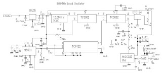
This 860 MHz Phase Locked Loop (PLL) oscillator circuit is designed for a 1200 MHz transverter's local oscillator with 435 MHz rigs. The oscillator circuit utilizes Toshiba PLL synthesizer ICs. The TC9122P is a user-friendly preset counter for determining...
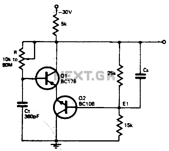
The timing resistor R can be adjusted to any value between 10 kΩ and 50 MΩ to achieve a frequency range from 400 kHz to 100 Hz. Connecting the timing resistor to the collector of Q1 ensures that Q1...