
Triangular Wave Generator Using Op-amp

The triangular wave generating circuit relies on the interplay between the comparator and the integrator. The comparator (first Op-Amp) compares two input voltages: a reference voltage and the output voltage from the integrator (second Op-Amp). When the output of the integrator exceeds the reference voltage, the comparator switches its output state, creating a square wave signal. This square wave signal is then fed into the integrator, which converts it into a triangular wave.
In practical terms, the circuit can be set up with the following components:
1. **Op-Amps**: Two LM741 operational amplifiers are used for the comparator and integrator functions.
2. **Resistors**: Appropriate resistor values are needed to set the gain for the comparator and to define the time constant for the integrator. The resistor values will determine the frequency and amplitude of the triangular wave.
3. **Capacitor**: A capacitor is connected to the output of the comparator and the input of the integrator to facilitate the integration process. The capacitance value will affect the slope of the triangular wave.
4. **Power Supply**: The Op-Amps require a dual power supply (positive and negative) to operate effectively.
When designing the circuit, careful consideration must be given to the feedback network in the integrator to ensure stability and prevent oscillations. The output of the integrator will produce a linear ramp up and down, which, when viewed over time, creates the characteristic triangular waveform.
Overall, this circuit is widely used in waveform generation applications, signal processing, and function generator designs, providing a reliable means of producing triangular waveforms for various electronic applications.This is a circuit diagram of the triangular wave producing circuit. We can produce the triangular wave with a series of two Op-Amp. You can use the LM741 op-amp. Op-amp first (left) is a series of comparison (comparator) while the Op-Amp circuit second (right) is the integrator. example : initial condition at the output 2 is negative, then output 1 will be positive, after passing through the integrator, the voltage at the output 2 is a reduction (negative slope). The following is a schematic drawing: 🔗 External reference
Related Circuits
In the image above, Oscium's iMSO-104 oscilloscope is measuring the output waveform of an infrared receiver (IR Rx). The iPad and iMSO serve as the oscilloscope to measure the receiver's output signal as the alignment between the transmitter and...
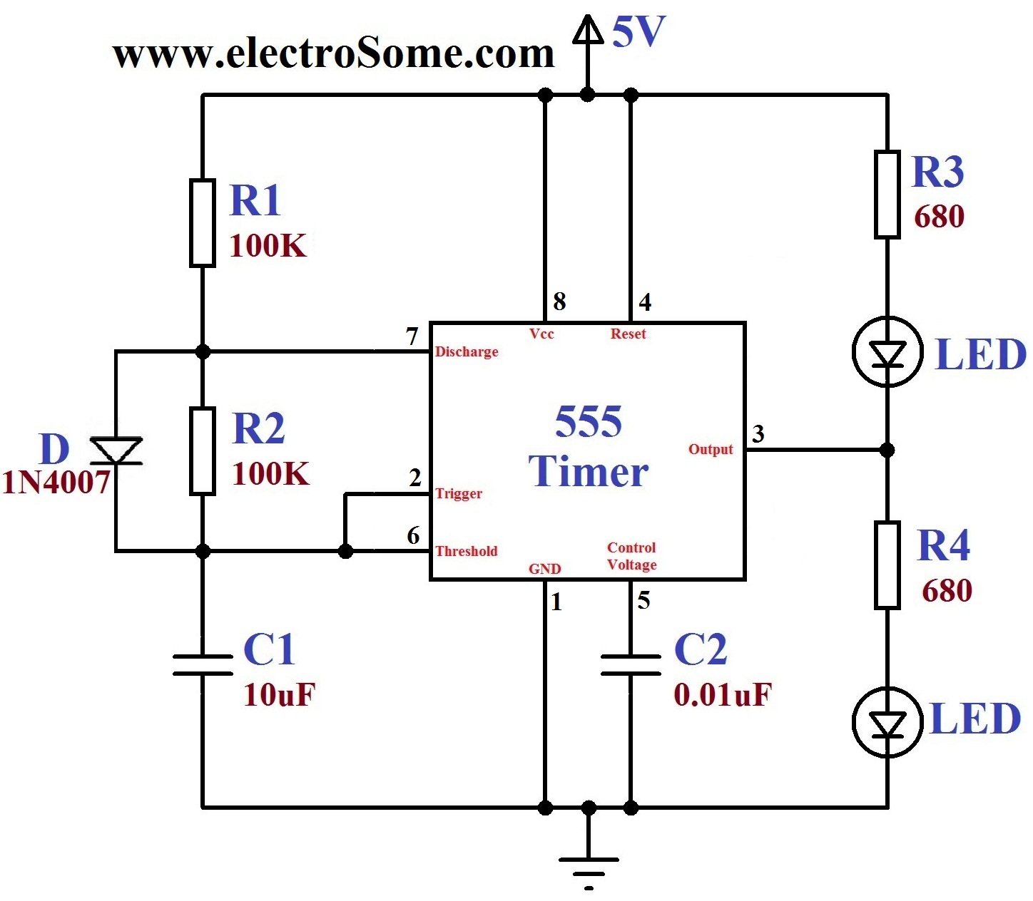
A dancing light can be easily constructed using a 555 timer wired in astable mode. This circuit alternately blinks two LEDs with a certain delay and can be modified to include additional LEDs or to control incandescent lamps. The...
The circuit is a temperature-to-pulse-width converter. The LM3524 is used to convert the output of an LM135 temperature transducer into a pulse width that can be measured by a digital system, such as a microprocessor-controlled data acquisition system. In...
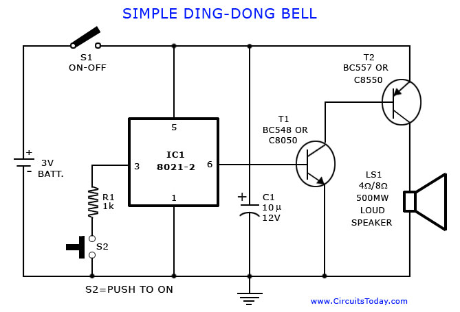
A tone generator circuit, which can be used to create a simple calling bell circuit, is illustrated here. It is constructed using the 8021 integrated circuit (IC), which includes built-in circuitry for producing a "ding-dong" sound. The tone generator circuit...
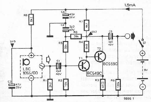
This electret microphone amplifier is constructed using standard electronic components. It is designed to work with an electret microphone capsule, although it can also accommodate a dynamic microphone that has low resistance. The circuit operates with a supply voltage...
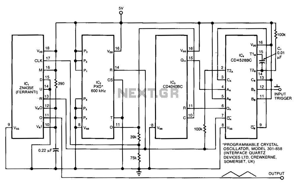
The ramp generator serves as a cost-effective alternative to commercial function generators, offering a more linear and repeatable output compared to traditional analog integrators. This circuit produces a triangle waveform in burst mode, generating two cycles of 10.24 ms...