
Temperature To Pulse Width Converter Circuit Using LM3524

The temperature-to-pulse-width converter circuit operates by utilizing the linear voltage output of the LM135 temperature sensor, which provides a voltage that varies with temperature. This voltage is fed into the operational amplifier (A1), configured to amplify the signal to a suitable level for the LM3524. The LM3524 is a versatile PWM controller that generates output pulses whose width is proportional to the input voltage, allowing for precise temperature measurement and control.
The circuit's feedback mechanism plays a crucial role in maintaining linearity in the output pulse width. By integrating the output of the LM3524 and feeding it back to the negative input of A1, the circuit stabilizes the output pulse width against fluctuations in temperature, ensuring accurate readings. The gain trim potentiometer allows for fine-tuning of the output, accommodating variations in component tolerances and ensuring that the pulse width corresponds accurately to the temperature range of interest.
The inclusion of a 1000 pF capacitor aids in loop stability by compensating for phase shifts that may occur in the feedback loop, thus preventing oscillations that could lead to inaccurate pulse width outputs. Additionally, the LM358 operational amplifier's ability to operate with input voltages close to ground enhances the circuit's sensitivity, allowing it to detect small changes in temperature effectively.
The output from pin 3 of the LM3524 serves a dual purpose; it provides a pulse that can trigger digital counters or microcontroller inputs, facilitating the integration of the temperature sensing circuit with digital systems for data logging or control applications. The overall design of this circuit exemplifies a well-thought-out approach to converting temperature readings into a format suitable for digital processing, enabling efficient and accurate temperature monitoring and control.The circuit is temperature to pulse width converter. The LM3524 to convert the output of an LM135 temperature transducer into a pulse width which can be measured by a digital system, such as a microprocessor controlled data acquisition system. In this circuit, the LM135`s temperature-dependent output (10 mV/ °K) is divided down and applied to A1`s
positive input. This moves A1`s output high, driving the input to the LM3524`s pulse width modulation circuitry. The LM3524 pulse-width output is clipped by the LM185 reference and integrated by the 1 MW-0. 1 µF combination. The DC level across the 0. 1 µF capacitor is fed back to A1`s negative input. This feedback path forces the LM3524`s output pulse width to vary in a highly linear fashion according to the potential at A1`s positive input. Here is a schematic drawing: The overall temperature to pulse width scale factor is adjusted with the gain trim potentiometer.
The 1000 pF capacitor provides stable loop compensation. A1, an LM358, allows voltages very close to ground to be sensed. This provides greater input range than the LM3524`s input amplifier, which has a common mode range of 1. 8 3. 4V. The oscillator output pulse at pin 3 may be used to reset counters or other digital circuitry because it occurs just before the output pulse width begins.
🔗 External reference
Related Circuits
This decibel meter circuit responds to sound pressure levels ranging from approximately 60 to 70 dB (decibels). The sound is captured by an 8-ohm speaker and amplified using a transistor stage along with an LM324 operational amplifier section. A...
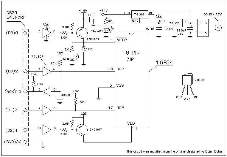
A universal Windows-based software designed to work with any serial programmers for the PIC16F84, known as WPicProg16 V1.20. It is recommended to build this programmer before starting various interesting projects with the F84. Some PIC programmers support in-circuit programming,...
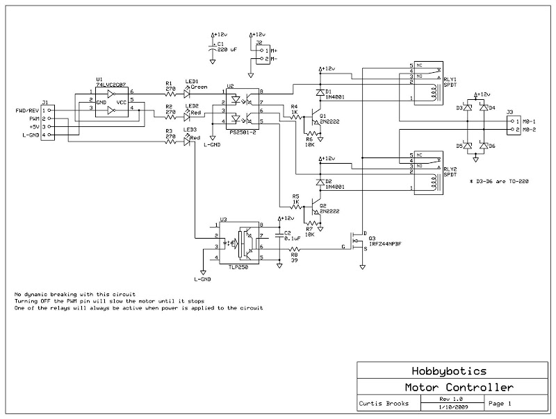
Develop a cost-effective high-current circuit that utilizes PWM. The design includes flyback diodes to protect the MOSFET from the back EMF generated by the motor when the power is switched on and off via the PWM signal. This configuration...
This 5-volt Switch Mode Power Supply circuit utilizes an integrated circuit (IC) from National Semiconductor, which specializes in the production and design of ICs for switch-mode power supply applications. The 5-volt Switch Mode Power Supply (SMPS) circuit is designed to...
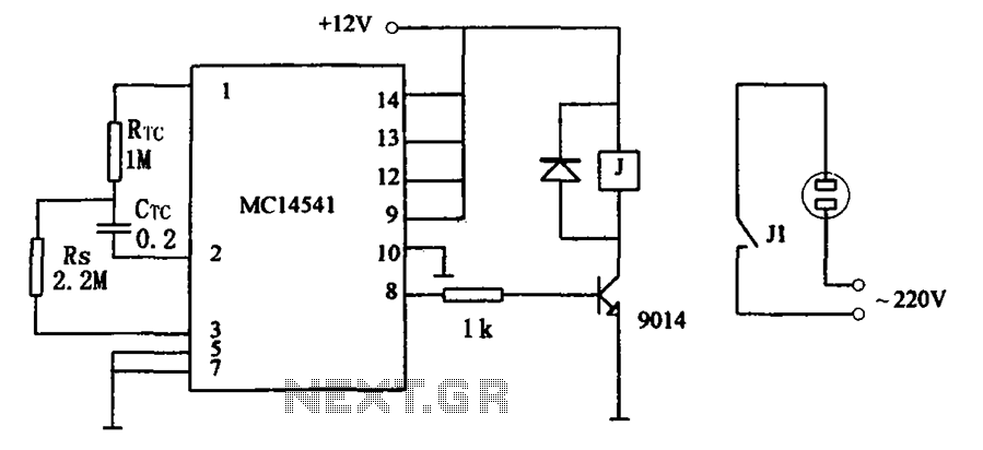
The circuit illustrated in FIG MC14541 is a straightforward timing circuit utilizing the MC14541 integrated circuit (IC). By adjusting the parameter map, the timing can be set for a duration of 3 hours, with options to select various RTC,...
The IR photo transistor Q1 (Radio Shack 276-145A) or a similar component is connected to the set input (pin 6). It is essential to shield the photo transistor from direct light to ensure that the voltage at the set...