
USART + Serial Comm with PC

The project involves establishing serial communication between a microcontroller and a personal computer (PC) using the Universal Synchronous/Asynchronous Receiver-Transmitter (USART) interface. The primary objective is to send a basic "Hello World" message from the microcontroller to the PC, allowing for verification of the communication setup.
To implement this, the following components and steps are necessary:
1. **Microcontroller Selection**: Choose a microcontroller that supports USART functionality. Common options include the ATmega series, PIC microcontrollers, or STM32 families.
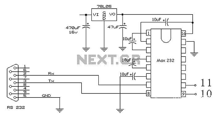
2. **Circuit Design**:
- Connect the microcontroller's TX (transmit) pin to the RX (receive) pin of a USB-to-serial converter or directly to the PC's serial port if available.
- Connect the microcontroller's RX pin to the TX pin of the USB-to-serial converter.
- Ensure common ground between the microcontroller and the PC for proper signal integrity.
3. **Software Configuration**:
- Initialize the USART module on the microcontroller. This involves setting the baud rate, character size, stop bits, and parity as per the requirements of the PC's serial communication settings (commonly 9600 baud, 8 data bits, no parity, and 1 stop bit).
- Write a simple program to send the string "Hello World" through the USART. This typically involves loading the string into a buffer and using the USART transmit function in a loop to send each character.
4. **Testing the Setup**:
- Use a terminal program on the PC (such as PuTTY, Tera Term, or the Arduino Serial Monitor) to open the corresponding COM port.
- Set the terminal settings to match the microcontroller's USART configuration.
- Upon powering the microcontroller, the terminal should display the "Hello World" message, confirming successful communication.
This basic setup serves as a foundational example for understanding serial communication using USART and can be expanded for more complex applications involving data exchange between the microcontroller and the PC.Create simple Hello world example of serial comm to a PC using microcontroller USART. 🔗 External reference
Related Circuits
I built this cable for my Casio QV-200 digital camera, it should work for many Casio models. It's basically an inverting buffer/converter to/from RS-232 voltage levels from/to CMOS levels. Why Casio didn't put this inside the camera like everyone...
I2C, pronounced "I squared C," stands for Inter-Integrated Circuit. This protocol was developed by Philips Semiconductors around 1992 to facilitate easy communication between components on the same circuit board, achieving transfer rates of up to 400 kbit/sec. It utilizes...
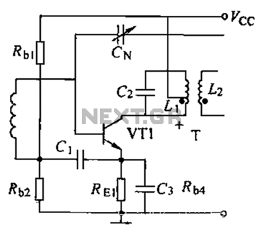
A common intermediate frequency amplifier circuit is presented, along with its components and parameters. The reference values for the components are as follows: 1) Transistors: VT1 to 3DG19, Vcc = 6V. 2) Resistance values: R1 = 50 kΩ, R2...
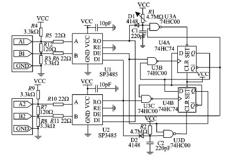
This article discusses the Lammert Bies - Computer Interfacing (RS485). The content is straightforward and informative. The components mentioned in this article can enhance understanding. For instance, readers can find and purchase RS485 components. The article also covers the...
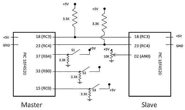
The 51 microcontroller features a full-duplex serial communication port, enabling straightforward serial communication between the microcontroller and a computer. However, certain conditions must be met for effective communication, such as the computer's serial port operating at RS232 levels while...
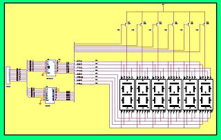
This hardware is designed to display the number of cars in a parking lot. The system utilizes a six-segment display; however, a single display is sufficient for the intended function. It employs the segment driver IC SN7447AN along with...