
I2C communication between PICs
i2c_start(); //begin transmission
i2c_write(0x14); //select address of device to communicate with
i2c_write(data); //send actual data
i2c_stop(); //terminate communication
For the slave PIC, it is necessary to define the output pins, assign the device name, and enforce hardware I2C communication. The device is randomly assigned the name 0x14, but it could be any even hexadecimal number, with a few exceptions noted in the code.
To read from the slave, the first byte sent is the address of the slave. The second byte corresponds to the location of the requested data on the slave. Communication is terminated before being restarted.
i2c_start (); //begin communication
i2c_write (0xa0); //send slave address
i2c_write (0x02); //request slave internal memory address for analogue data
i2c_stop(); //stop write cycle to shift to read cycle
i2c_start (); //send repeated start command to begin read cycle
i2c_write (0xa1); //add 1 to the address to indicate a read bit
result = i2c_read(0); //read analogue information from the slave
i2c_stop (); //terminate communication
output_d(result); //display analogue
The I2C protocol is a versatile and efficient means of communication in embedded systems, particularly when multiple devices need to interact with minimal wiring. The protocol's simplicity allows for easy integration of various components, making it a popular choice in a wide range of applications, including sensor data acquisition, device control, and more. The use of pull-up resistors is critical in maintaining signal integrity, ensuring reliable communication between the master and slave devices. Proper implementation of the start and stop commands is essential for effective data transfer, as it delineates the boundaries of communication sessions.I2C is pronounced "I squared C" and stands for Inter-Integrated Circuit. This protocol was designed by Phillips Semiconductors around 1992 to allow easy communication between components on the same circuit board and can achieve transfer rates of up to 400 kbit/sec. Is is a 2 line (plus common ground) communication method for one master device to c ontrol up to 112 slave devices. While it is possible to have multiple masters on the same I2c bus, this page will only deal with a one master configuration. The two lines are named SCL and SDA where SCL is the CLock line and SDA is the DAta line. The PIC 4520 is designed to use pin 18 as SCL and pin 23 as SDA for hardware I2C. Note that pin 18 is one of the only pins not accessible on the prototyping board. An additional wire can be added as shown in the example image. It is possible to use lines accessible from the prototyping board to communicate via software I2C, but this has data rates of less than one fourth those of hardware I2C and will therefore be omitted.
I2C requires the lines to be high unless the master or the slave is pulling the line down, so you will need to use pull up resistors on both the clock and data lines. The data line can only change while the clock line is low. The data line is only read when the clock line is high and therefore 1 bit can be transferred per cycle of the clock line.
The master is initially sends a start bit followed by the 7-bit address of the slave it wishes to communicate with. The next bit represents whether it wishes to write(0) to or read(1) from the slave. The slave then responds with an acknowledge bit. The transmission continues according to whether the master is attempting to read to or write from the device.
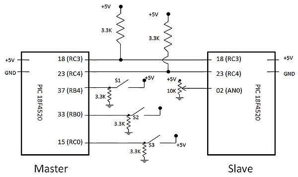
Below is a simple circuit diagram showing the master PIC with 2 close button switches. Note that pin 18 (RC3) is not brought out to the circuit board, but a wire can be soldered next to the PIC itself. Both SDA and SCL need pull up resistors as either the master or the slave can hold the line low to stop communication.
To communicate with a device, we use the following lines of code where 0x14 is the device name. The first line is the issuing of the start command and this forces all slave devices on the bus to wait for their address. The next write command is the address of the slave. The following byte is the data being sent to the slave. All communication must terminate with a stop command or the line will remain open and no future communication is possible until the command is given.
i2c_start(); //begin transmission i2c_write(0x14); //select address of device to communicate with i2c_write(data); //send actual data i2c_stop(); //terminate communication For the Slave PIC, we first need to define the output pins, define the name of the device and force hardware I2C communication. This device was randomly assigned name 0x14, but could have been just about any even hex number with a few exceptions noted below code.
0000 000 1 START byte - for slow micros without I2C h/w 0000 001 X CBUS address - a different bus protocol 0000 010 X Reserved for different bus format 0000 011 X Reserved for future purposes 0000 1XX X Hs-mode master code 1111 1XX X Reserved for future purposes 1111 0XX X 10-bit slave addressing To read from the slave, the first byte sent is the address of the slave. The second byte is the location of the data on the slave being requested. The communication is terminated before being restarted. i2c_start (); //begin communication i2c_write (0xa0); //send slave address i2c_write (0x02); //request slave internal memory address for analogue data i2c_stop(); //stop write cycle to shift to read cycle i2c_start (); //send repeated start command to begin read cycle i2c_write (0xa1); //add 1 to the address to send a read bit result = i2c_read(0); //read analogue information from the slave i2c_stop (); //terminate communication output_d(result); //display analogue
🔗 External reference
Related Circuits
Watching the time on a mobile phone in the dark can cause discomfort due to the strong contrast between bright and dark backlighting. To address this issue, the "ICON" model is utilized, which operates in standby mode with a...
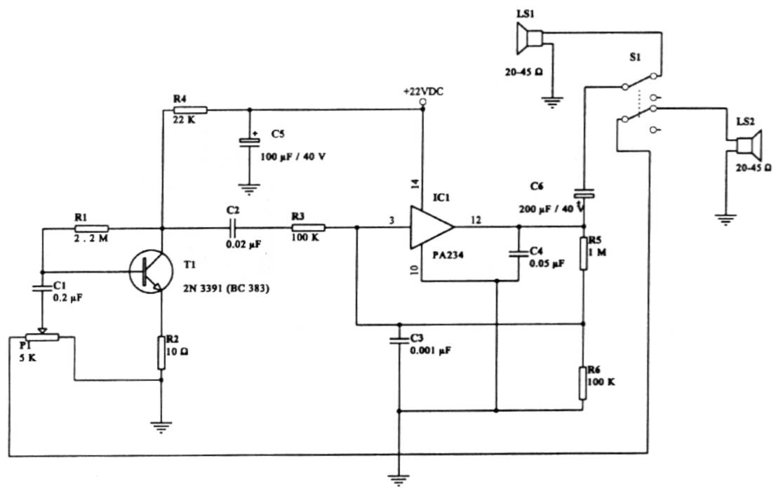
This intercom circuit is versatile and can be utilized in various applications. It operates at 22V, although it may function at a lower voltage (experimental testing is suggested). The circuit employs a loudspeaker with an impedance of 20-45 Ohms...
This kit is based on an original design by Jan G0BBL and serves as a versatile replacement for the older "Rocky" serial interface kit. It includes control of the programmable oscillator on the V6, 3 RXTX (and the older,...
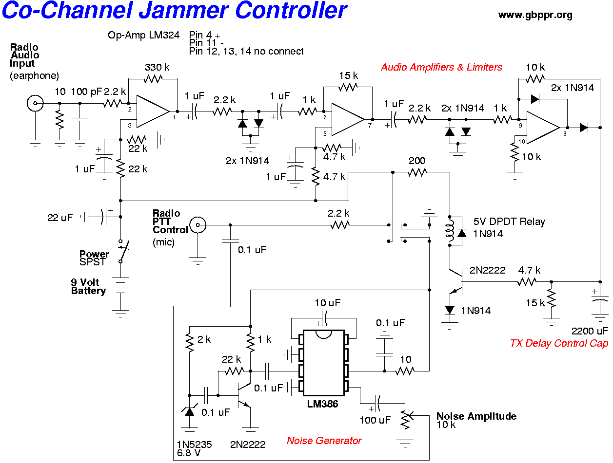
A barrage noise jammer for VHF/UHF communications is constructed using an old TV tuner. The local oscillator of the tuner is tapped and amplified. The voltage tuning line of the tuner is combined with a sweeping, random noise signal. The...
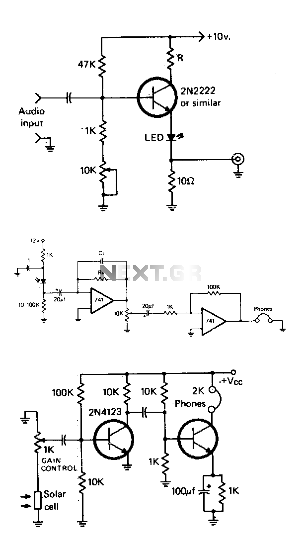
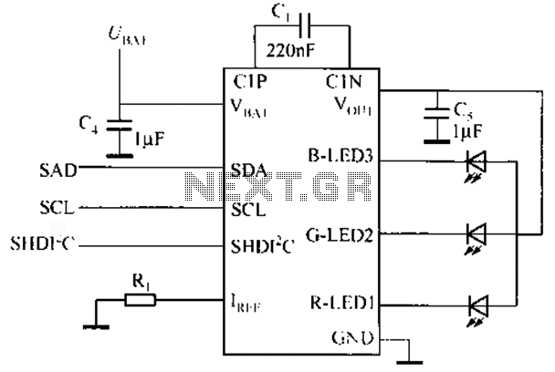
The simple modulator stage will accommodate most common LEDs. By adjusting the potentiometer, the bias of the transistor is varied until the LED is at its half output point. Then, audio will cause it to vary above and below...
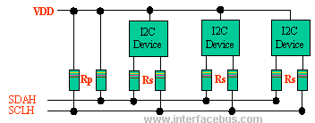
The I2C bus employs a bi-directional Serial Clock Line (SCL) and Serial Data Line (SDA). Both the SCL and SDA lines are pulled high using a pull-up resistor (Rp). An optional resistor (Rs) is utilized for ESD protection in...