
Common intermediate frequency amplifier circuit having a circuit and on the radio
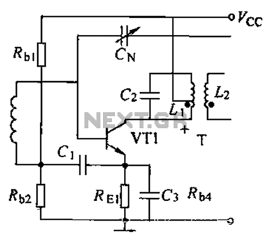
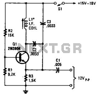
The intermediate frequency (IF) amplifier circuit is essential in radio communication systems, where it amplifies signals after the initial frequency conversion. The circuit employs a transistor configuration, specifically the 3DG19, which operates at a supply voltage of 6V. The transistor's role is to amplify the incoming IF signal while maintaining linearity and minimizing distortion.
The resistors in the circuit are carefully selected to set the biasing conditions for the transistor. R1, with a value of 50 kΩ, is connected to the base of the transistor, providing the necessary base current for operation. R2, valued at 10 kΩ, is used for feedback, enhancing the stability of the amplifier. The emitter resistor Re, at 1 kΩ, plays a critical role in stabilizing the operating point of the transistor against variations in temperature and supply voltage.
Capacitance values are also crucial in determining the frequency response of the amplifier. C1, which is 0.01 μF, acts as a coupling capacitor, allowing AC signals to pass while blocking DC components. C2, with a value of 200 pF, and C3, at 6 pF, are used for bypassing and filtering, ensuring that unwanted high-frequency noise does not affect the amplifier's performance.
The simplicity of this circuit design allows for easy implementation while providing robust performance characteristics. The stability of the IF amplifier is further ensured by the careful selection of component values, which allows it to operate effectively in various conditions. Overall, this intermediate frequency amplifier circuit is a reliable solution for enhancing signal clarity in radio applications. Common intermediate frequency amplifier circuit having a circuit and on the radio as shown in FIG. Component Parameters Reference values are as follows: 1) transistors: VT1 to 3DG19, Vcc 6V. 2) Resistance: Rhl - 50kCZ, Rh2 lOkfl, Re, a lkfl. 3) Capacitance: cl-G o OlyF. Pakistan 200pF, CN 6pF. And having an intermediate frequency amplifier circuit and due to the addition circuit, to ensure stable operation of the IF amplifier, and the circuit is simple, is a kind of good performance amplifier.
Related Circuits
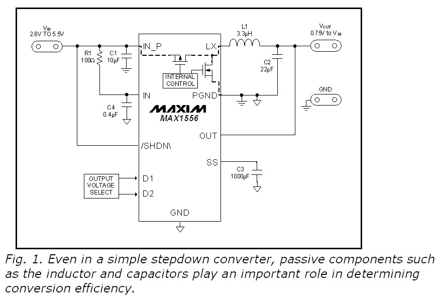
This blog provides insights into SMPS (Switched-Mode Power Supply) circuit diagrams. It offers valuable information for those interested in understanding this topic. Switched-Mode Power Supplies (SMPS) are crucial in modern electronic devices due to their efficiency and compact design. An...
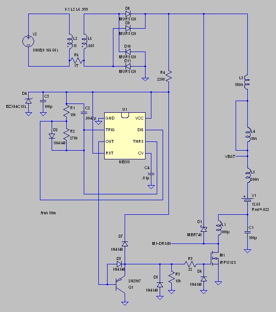
Desulfation is the process of reversing sulfation that occurs in a lead-acid battery over time. Desulfation partially restores the battery's ability to hold a charge, which is diminished due to sulfation. Desulfation is a critical maintenance procedure for lead-acid batteries,...
This is a small audio amplifier, similar to those used in small transistor radios. The circuit draws approximately 30 milliamps from a 9-volt supply and consists of two stages. The first stage is the input stage using a 2N3053...
A simple oscillator for intermediate frequency (IF) alignment at 455 kHz can be useful in field testing or in scenarios where a standard signal generator is available. The inductor (L1) should resonate at the desired output frequency with the...
The circuit below illustrates generating a single positive pulse which is delayed relative to the trigger input time. The circuit is similar to the one above but employs two stages so that both the pulse width and delay can...
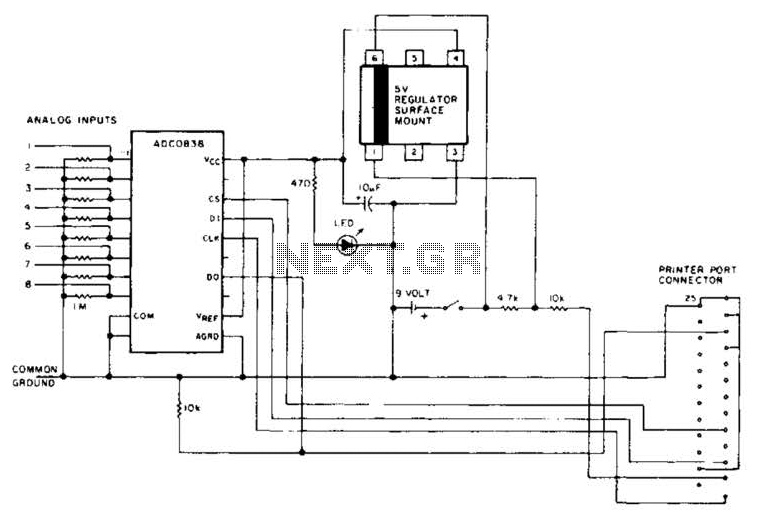
An A/D converter by National Semiconductor (ADC0838) converts 0 to 5 V analog inputs into a digital data format. A 9 V battery is utilized. The converter connects to the pointer port connector through a 25-pin connector. The ADC0838 is...