
Understanding FM transmitter circuit
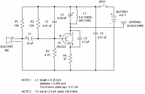
The Wireless FM Transmitter circuit utilizes an electret microphone as the primary audio input source. The electret microphone converts sound waves into electrical signals by varying its output current in response to sound pressure levels. The specified current of 200 µA, with a variation of ±3 µA, causes a corresponding change in voltage across R1, which is a critical component in determining the signal level fed into the circuit.
When sound waves strike the microphone, the resulting change in current through R1 alters the voltage across the microphone, effectively modulating the audio signal. This modulated signal is then coupled through capacitor C1, which blocks any DC component while allowing the AC audio signal to pass through to the base of the transistor. The transistor acts as an amplifier, with its base biased at approximately 2V through resistors R2 and R3, facilitating proper operation within the active region.
The voltage across R4 is influenced by the voltage at the base of the transistor, which changes in response to the audio signal. When no signal is present, the voltage across R4 is determined by the biasing conditions, specifically Vb - 0.7V, resulting in a steady-state voltage of 1.3V. As the audio signal modulates the base voltage, the current through R4 changes, which subsequently affects the tank circuit's behavior.
The tank circuit, comprising an inductor and capacitor, is responsible for determining the transmission frequency. The modulation of the base voltage influences the tank circuit's resonant frequency, thus allowing for frequency modulation. In this context, it is important to note that true frequency modulation requires a change in the frequency of the carrier wave, which is achieved through variations in the tank circuit's parameters, rather than merely amplitude changes.
Capacitor C3's role in the circuit is critical; it may serve to stabilize the collector-emitter voltage or help filter high-frequency noise. It can also function as a bypass capacitor, improving the performance of the circuit by providing a low impedance path for AC signals while maintaining a stable DC voltage. Bypass capacitors are typically connected to ground to ensure they effectively filter out unwanted AC components from the power supply, thus enhancing the overall stability and performance of the transmitter circuit.
Understanding these components and their interactions is essential for grasping the operation of the Wireless FM Transmitter and ensuring effective modulation and transmission of audio signals.Wireless FM Transmitter. The site has some explanation on how the circuit works, however I`m not sure about a few things, including the electret mic & how the frequency modulation takes place. The electret microphone has a current of 200uA which changes by +- 3 uA depending on sound waves. This sets the voltage across R1 to 2V and the voltage acro ss the mic to 4 volts. As the sound hits the mic the current through R1 increases slightly reducing the voltage across the mic. Is that what is happening This changing voltage is passed on by the coupling cap, C1 to the base of the transistor, which is biased by R2 & R3 to approx 2V.
The voltage across R4 with no signal on the mic will be Vb - 0. 7 (drop across vbe), 1. 3 volts. As the voltage at b changes R4 will change by the same amount. This change in voltage is seen at the base of the tank circuit. And the signals voltage is increased/decreased. Isn`t this what happens in AM As wouldn`t the capacitance need to change in order to get Frequency modulation And if it was amplitude modulation occuring in the FM spectrum, then how would a radio receiver be able to demodulate the signal At this point I`m not sure what is happening at the capacitor C3, what is that doing Is it holding CE at a fixed voltage And is it along with capacitor C2 considered a bypass capacitor Or do bypass capacitors need to be connected to ground 🔗 External reference
Related Circuits
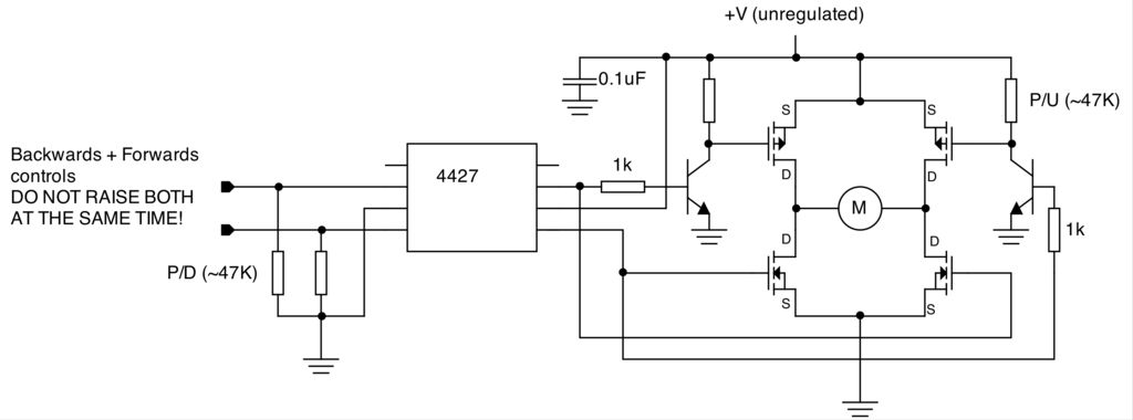
To create a versatile and generic microcontroller board, the information provided thus far is sufficient. It covers the essential components needed to achieve this. The design of a microcontroller board requires careful consideration of various factors to ensure versatility and...
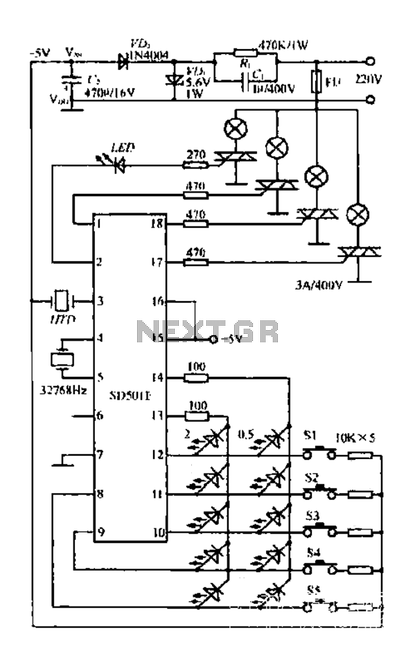
The FIG SD501E is a J tie fan integrated circuit (IC) characterized by progressive timing and three operational modes: strong, medium, and weak. It features three types of output settings and includes an electrical swing mechanism. The device is...
The inquiry pertains to the connection of lights that flash when a phone rings. This feature is particularly beneficial in noisy environments, such as workshops, where hearing the phone may be difficult. A device designed for this purpose is...
Developed as an interface between the General Instruments AY-3-8500-1 TV game chip and the antenna terminal of a TV set. Adjust capacitor C1 to the frequency of an unused channel to which the receiver is set for playing games....

The CMOS 4060 is a 14-bit binary counter; however, only ten of these bits are connected to output pins. The 4060 also includes two inverters, which are connected in series across pins 11, 10, and 9. Together with resistors...
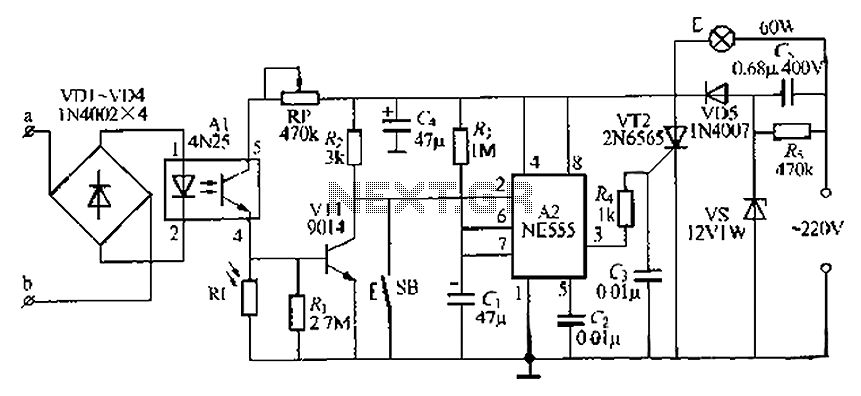
The lamp base circuit integrates an NE555 timer and optocouplers to automatically activate the light when a phone call is received at night. The lamp will self-extinguish after a delay. Additionally, a switch allows manual control of the lamp....