
onoff 24 hours timer circuit schematic
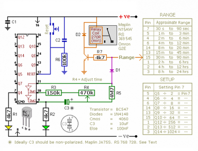
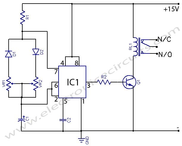
The CMOS 4060 is a versatile integrated circuit that combines a binary counter and an oscillator, making it suitable for various timing applications. The counter operates by counting the oscillations generated by the oscillator circuit. The oscillator is formed by the two inverters and the passive components R3, R4, R5, and C3, which determine the frequency of oscillation. The output frequency can be finely tuned through R4, allowing for precise timing control.
The ten output pins of the counter can be utilized to indicate the current count, enabling the design of digital clocks, timers, and frequency dividers. The ability to switch the transistor via the output pins allows for the control of larger loads, such as relays, which can be used to switch on or off various devices in response to the counter's state.
In single-shot mode, the configuration with diode D1 prevents further oscillations once the desired count is reached, making it ideal for applications requiring a one-time event trigger. Conversely, by excluding D1, the circuit can operate in a continuous mode, providing a repetitive output signal that can be used for applications such as pulse-width modulation or regular timing signals.
The CMOS 4060's flexibility and ease of use make it a valuable component in electronic designs, allowing engineers to create efficient and reliable timing solutions in a compact form factor.The Cmos 4060 is a 14-bit binary counter. However - only ten of those bits are connected to output pins. The 4060 also has two inverters - connected in series across pins 11, 10 & 9. Together with R3, R4, R5 and C3 - they form a simple oscillator. While the oscillator is running - the 14-bit counter counts the number of oscillations - and the stat e of the count is reflected in the output pins. By adjusting R4 you can alter the frequency of the oscillator. So you can control the speed at which the count progresses. In other words - you can decide how long it will take for any given output pin to go high. When that pin goes high - it switches the transistor - and the transistor in turn operates the relay. In single-shot mode - the output pin does a second job. It uses D1 to disable the oscillator - so the count stops with the output pin high. If you want to use the timer in repeating mode - simply leave out D1. The count will carry on indefinitely. And the output pin will continue to switch the transistor on and off - at the same regular time intervals.
🔗 External reference
Related Circuits
The provided schematic diagram illustrates an LM741 light/dark sensor circuit, derived from the 741 Op-Amp Tutorial by Tony van Roon. The ECG128/NTE128 transistor can be replaced with any NPN transistor that meets the necessary gain and current specifications for...
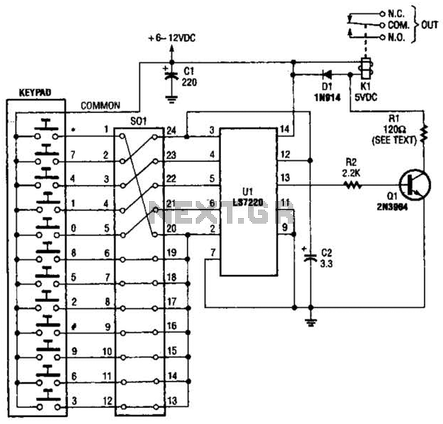
A block pinout diagram of the LS7220 keyless-lock IC is presented. The keypad must provide each key with a contact to a common connection. In this instance, the common connection is linked to the positive supply rail, allowing a...
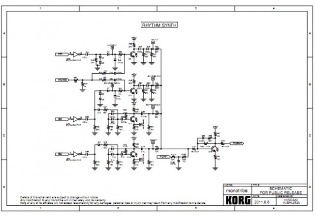
Korg has released schematics for the analog drum synthesis section of its Monotribe synthesizer and step-sequencing rhythm machine. The schematics focus on the components responsible for generating drum sounds, which are the most interesting and modifiable aspects of the...
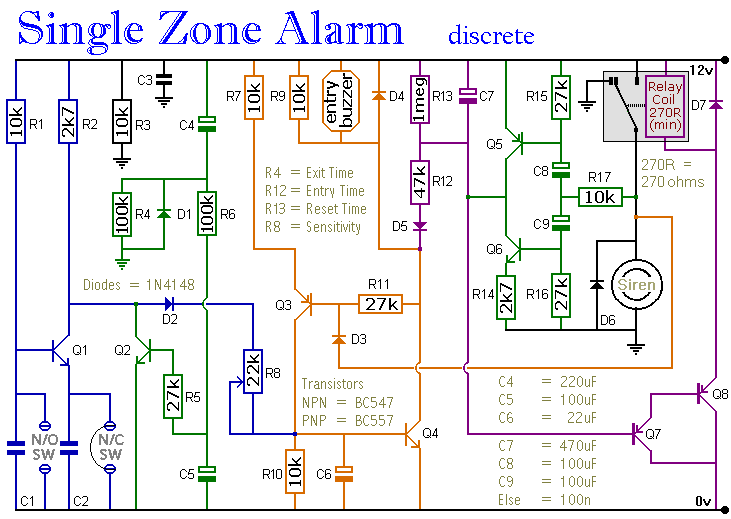
The circuit includes automatic exit and entry delays, a timed bell cut-off, and a system reset feature. It accommodates both normally-open and normally-closed switches, making it compatible with standard input devices such as pressure mats, magnetic reed contacts, foil...
555 Timer with On-Off Delay Circuit. This circuit utilizes the commonly available 555 integrated circuit (IC) to create a timer that allows for time adjustment in both on and off states. The 555 timer is a versatile device widely used...
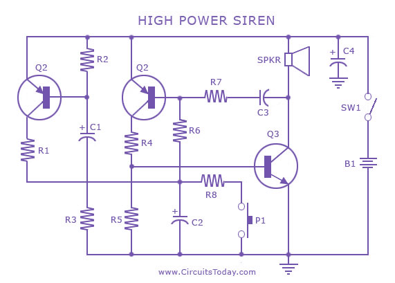
A siren circuit diagram that generates a strong, high-power siren or alarm sound using complementary transistor pairs BC 557 and BC 337, arranged as an oscillator. The described siren circuit employs a pair of complementary transistors, BC 557 (a PNP...
Warning: include(partials/cookie-banner.php): Failed to open stream: Permission denied in /var/www/html/nextgr/view-circuit.php on line 713
Warning: include(): Failed opening 'partials/cookie-banner.php' for inclusion (include_path='.:/usr/share/php') in /var/www/html/nextgr/view-circuit.php on line 713