
Telephone control automatic lamp circuit 2
The circuit operates by utilizing an NE555 timer in a monostable mode, which is triggered by the current induced in the telephone line when a call is received. The optocoupler, specifically a 4N4 model, plays a crucial role in isolating the telephone line from the rest of the circuit while allowing signal transmission. The built-in LED of the optocoupler illuminates when a phone call is detected, which in turn activates the photodiode, signaling the change in state to the transistor VT1. This transistor acts as a switch, controlling the flow of current to the NE555 timer.
Upon activation, the NE555 timer generates a high output signal for a predetermined duration, which is set by the resistor-capacitor (RC) network connected to its pins. During this time, the second transistor (VT2) is turned on, allowing current to flow to the lamp, thereby illuminating it. The lamp remains lit for a brief period even after the call is disconnected, as the timer maintains the output high until the RC timing cycle completes.
The circuit includes a manual switch (SB) that allows users to turn on the lamp regardless of the phone call status. Pressing this switch sends a low signal to the NE555 timer, temporarily overriding the automatic function and ensuring the lamp turns on. The design incorporates resistors (R1 and RP) that adjust the sensitivity of the light control circuit, ensuring that the lamp only activates in low-light conditions. This feature is essential for preventing the lamp from turning on during the day due to ambient light.
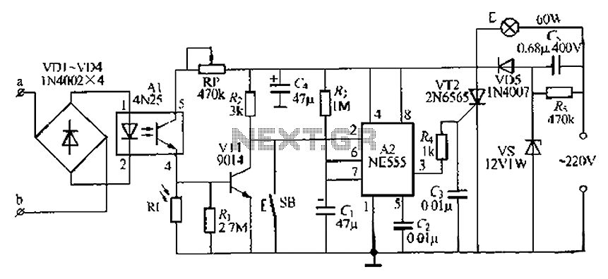
Overall, this circuit represents an efficient solution for automatic lighting control in response to incoming phone calls, particularly useful in scenarios where manual operation is inconvenient. The combination of the NE555 timer, optocouplers, and transistors provides a reliable and effective means of achieving this functionality. By phone automatically when the lamp base circuit NE555 and optocouplers constituted a call at night, light will automatically light up, hang up delay imi. About, self-extingui shing lamp. Good circuit also has an r- buttons switches usually require + F lights, just gently press the switch, the lamp can be automatically according to Hh imin. a, b end of the telephone line connected in the towel, do not have time to distinguish between positive and negative polarity of the string, the string will not affect its power to make the phone only constant T.
Usually no current telephone line through the optocoupler tuner Al (4N4,) the built-in light emitting diode will not light, corresponding to the photodiode off, namely the Al pin output low. VT1 is in the off state state, its collector is provider level, by the A2 C NF.555) consisting of Shin-shot at in a stable state, the output terminal pin output low level, the thyristor wr2 off, according to state lamp E does not shine.
When I hear an electric, then the owner of the buckle or hook dialing, the current through the telephone line, Al built-in LEDs light emitting corresponding photodiode is turned on, namely the Al feet lose. high. VT1 get base flow conduction, the collector output low, namely monostable touch flop pin input a negative Wing Chong A2, A2 is triggered flip temporarily set into the nervous, pin is output high, VT2 get sleepy gate trigger lU stream opened, fE namely BU bright.
As the phone rang Bi unmanned hook or kick after electric hook tongue, Al of O, feet secluded lose if the current account, containing arc tube off, the corresponding photodiodes recovery off state, VT1 also will be closed. At this time only by the power called R. To C. Seek power after about imijI after that AZs foot level l River to 2, + 3V.. Transient end trigger clamor turn stabilized exhausted, pin returns low, VT2 go missing trigger current, alternating current zero-crossing spot that is called off, the lamp F turns off.
When SB button to turn on the lights, turn on the lights lighting usually required, just click SB. feet to A2 anthropogenic input of people a low f, forcing A2 flipped into the temporarily exhausted, it can also make the point against the lamp E imin. Rl. And RP constituting the light control circuit. J for the two cases above process, it ensures that the circuit does not work during the day, only at night to r automatic light control only by telephone, thick section RP may light control sensitivity adjusting circuit.
This circuit RI. Installing more freedom, as long as it can make you can feel the natural light and small enough to have to worry about it being my lamp E itself exposed to light small disturbance.
Related Circuits
Incremental rotation or linear encoders are widely used, but they typically do not provide a direction signal. This design presents a straightforward method to detect forward or reverse direction. Incremental encoders usually generate two output signals, referred to as...
There is no substitute for sheer power—low-efficiency speakers, outdoor sound systems, or perhaps the full dynamic range of a high-power amplifier. Whatever the requirement, this super power module should meet the needs. The amplifier can be divided into three...
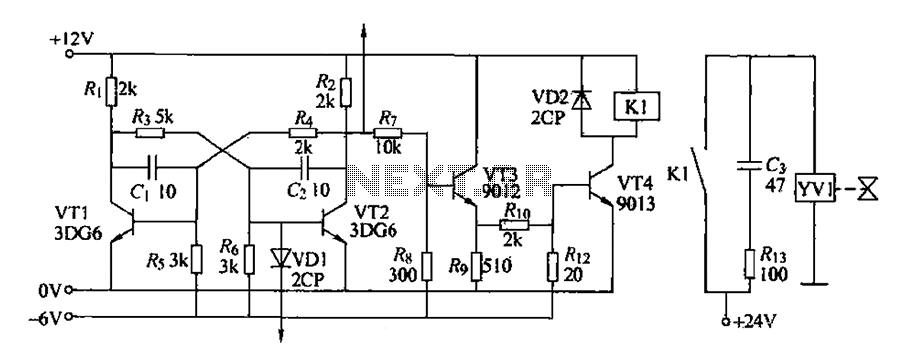
The circuit for detecting bad book binding is not illustrated. The solenoid valve is used to control the head of the YV1 mechanism for handling bad books. Under constant conditions, there is no positive signal indicating a bad book....

All of ACC's repeater and remote base products support the control of synthesized remote base transceivers. One form of frequency control supported is compatible with transceivers using thumbwheel frequency selection. The controllers supply BCD (binary coded decimal) formatted data...
As shown in the figure, D187 is a UART with its RX/TX signals connected through optocouplers N21, N22, and N29, providing complete optoelectronic isolation for the RS-485 communication interface receiver/transmitter D28 and microprocessor D211. D197 serves as a generator,...
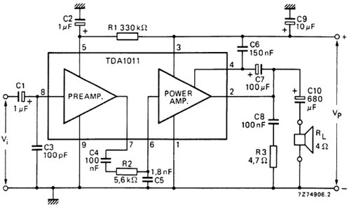
The following schematic illustrates the design of a 4 Watt Amplifier Circuit Diagram intended for portable radio applications, utilizing the TDA1011 integrated circuit from Philips Semiconductor. The 4 Watt Amplifier Circuit is designed to provide audio amplification in portable radio...