
Wireless Power Charger Schematic
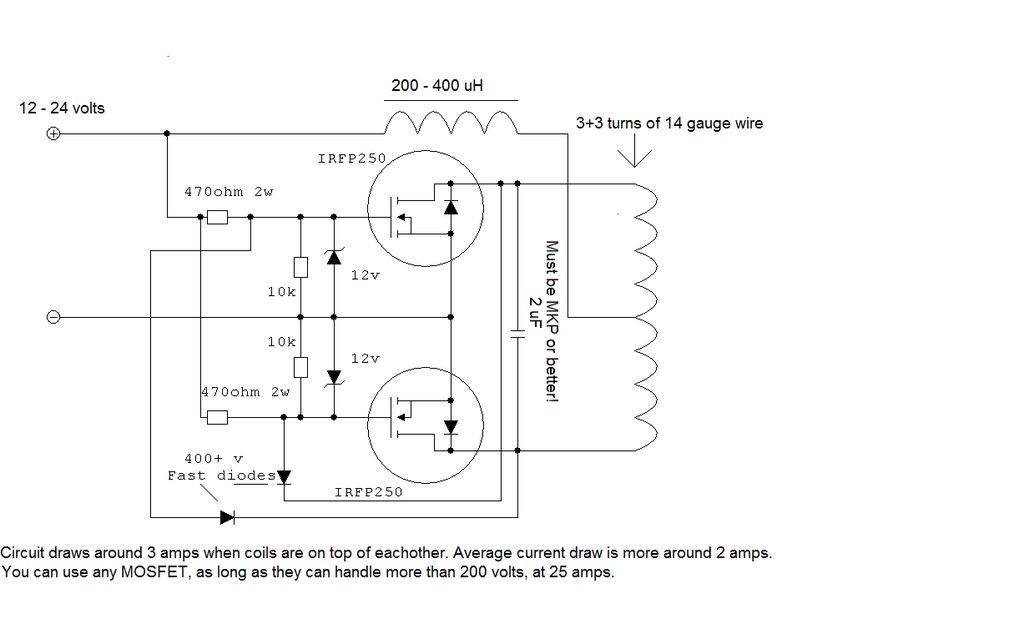
To build the circuit effectively, it is essential to adhere closely to the provided schematic diagram. This diagram serves as a visual guide, illustrating the connections between various components, including resistors, capacitors, diodes, and integrated circuits. Each component is labeled with its respective value and designation, ensuring clarity during assembly.
Begin by gathering all necessary components as indicated in the schematic. It is advisable to organize them systematically to streamline the assembly process. Pay attention to the orientation of polarized components, such as electrolytic capacitors and diodes, as incorrect placement can lead to circuit malfunction.
Once the components are prepared, start with the placement of the smallest components, typically resistors and small capacitors, onto the circuit board. This approach allows for easier handling and minimizes the risk of damaging larger components. Secure each component in place with solder, ensuring solid connections while avoiding cold solder joints.
After all components are soldered, inspect the circuit for any potential errors, such as misplaced components or solder bridges. A multimeter can be employed to test continuity and verify that connections are correct. Once the inspection is complete, power up the circuit gradually, monitoring for any unusual behavior.
In case of difficulties in identifying components or troubleshooting issues, consulting the schematic again or reaching out for assistance from knowledgeable sources can be beneficial. Proper documentation and a methodical approach will greatly enhance the likelihood of successful circuit assembly and functionality.To build it, just follow the schematic as shown. (If you need help, please, do not hesitate to message me!) If you`re having trouble identifying the.. 🔗 External reference
Related Circuits
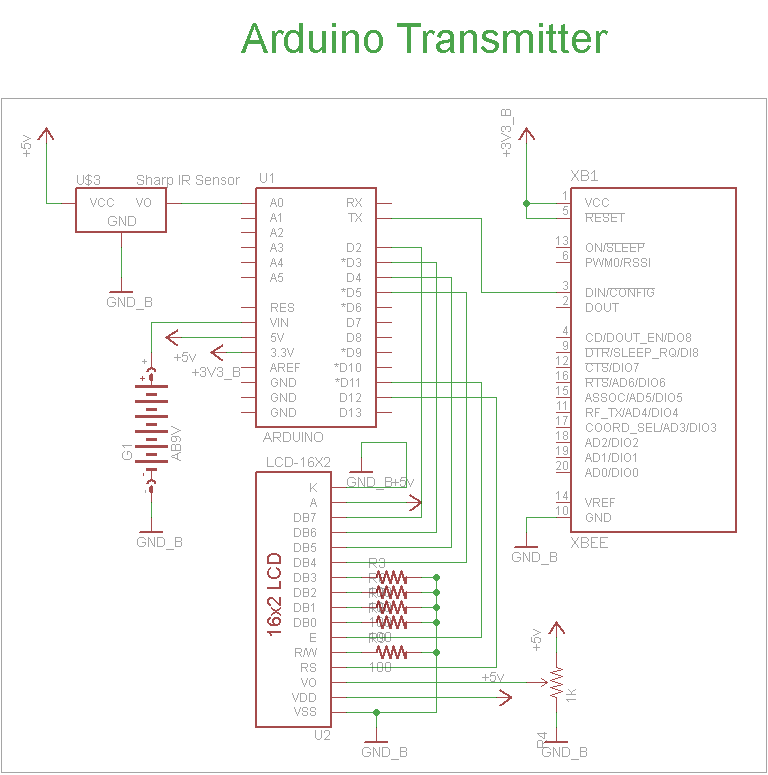
The schematic for the transmitter in this project consists of four main components: the Arduino UNO, the Sharp IR distance sensor, the XBee wireless modules, and a 16x2 LCD. The connections between these components are illustrated in the schematic....
This circuit is a compact +5V power supply that is beneficial for digital electronics experimentation. Inexpensive wall transformers with variable output voltage can be found at electronics shops and supermarkets. While these transformers are readily available, their voltage regulation...
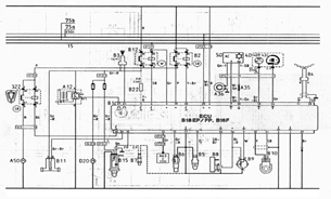
The following document contains information related to the electrical installation schematic diagram for the Volvo 440. It includes the wiring schematic for the Volvo 440, 460, and 480 series. The Volvo 440, 460, and 480 series vehicles feature a comprehensive...
The Jammer is a very small circuit and can fit inside a small plastic box with 9V battery inside. It can be very illegal if you attach an external antenna so don't. adjust frequency by turning trimmer. It is...
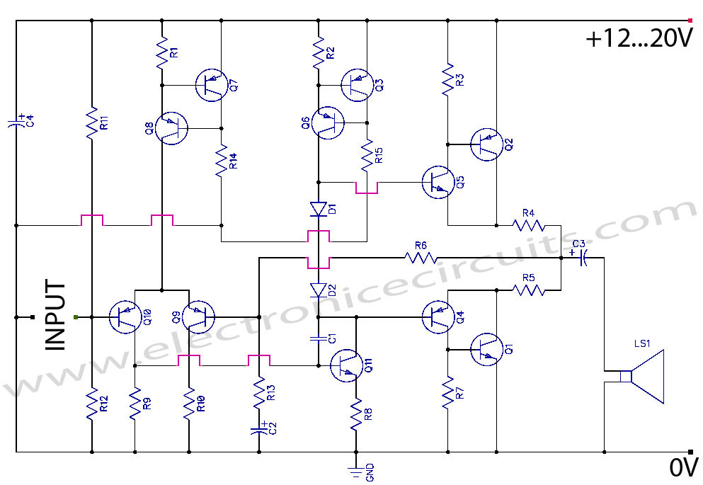
Discrete Class AB Transistor Audio Power Amplifier Circuit Diagram. This is a Class AB transistor power amplifier. It is a simple amplifier. The discrete Class AB transistor audio power amplifier is designed to provide efficient amplification of audio signals while...
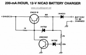
This NiCAD battery charger circuit charges the battery at 75 mA until it is fully charged, after which it reduces the current to a trickle rate. It can completely recharge a dead or unpowered battery in 4 hours, and...