
200mA/Hour 12V NiCAD Battery Charger
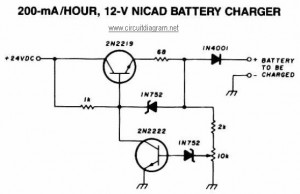
The following diagram represents a lead-acid battery charger circuit, which provides an initial voltage of 2.5 V per cell at 25 °C to facilitate rapid charging. The charging current decreases as the battery charges, and when it drops to 180 mA, the charging circuit reduces the output voltage. This regulated and adjustable battery charger circuit is capable of charging most NiCAD batteries. It is suitable for single cells or multiple battery cells connected in series or parallel, with a maximum voltage of 18 V. Power transistors Q1 and Q2 are configured as series regulators.
Additionally, a simple circuit diagram for a 12V car battery charger is available. This circuit is designed to prevent battery overcharging, which can lead to electrolyte loss due to evaporation. It monitors the battery's charge condition through a retroactive control circuit that applies a high charge when necessary. Furthermore, this battery charger circuit is intended for rechargeable lithium batteries, utilizing a constant current of 60 mA for AA cells, with a cutoff voltage of 2.4 V per cell, at which point charging must be terminated. The system is designed for multi-cell battery packs consisting of 2 to 6 series-connected cells. Lastly, a schematic diagram for a solar-powered mobile phone battery charger is provided. This circuit is engineered to charge the battery from a source with a lower voltage and should not be used to charge a battery with the same or lower voltage than that generated by the solar panel to ensure proper operation.This NiCAD battery charger circuit charges the battery at 75 mA until the battery is charged, then it reduces the current to a trickle rate. It will fully recharge a dead/unpowered battery in 4 hours and the battery can be left in the charger indefinitely.
To set the shut off point, connect a 270 ohm / 2 Watt resistor across the charge terminals a nd adjust the pot for 15. 5V across the resistor. Tags: 12V NiCAD battery Charger, 200mA/Hour NiCAD battery Charger, NiCAD battery Charger circuit, NiCAD battery Charger diagram, NiCAD battery Charger schematic, The following diagram is the schematic diagram of Ni-CAD Battery Charger circuit which featured with current and voltage limiting to keep the battery lifetime. The lamp L1 will be light brightly and the LED will be out when the battery is low and battery charging in progress, but the LED is very bright and the.
The following diagram is the circuit diagram of Lead-Acid battery charger. This circuit provides an initial voltage of 2. 5 V per cell at 25 ƒ to quickly charge the battery. The charging current decreases as the battery is charging, and when the current drops to 180 mA, the charging circuit reduces the output voltage of. This battery charger circuit is regulated and adjustable to make this circuit able to charge the mosto NiCAD battery.
This circuit will work for single cell or multi battery cell which connected with series/parallel connection. The maximum voltage of the batteries should be 18V maximum. Power transistors Q1 and Q2 are connected as series regulators. Here is a simple and easy to build circuit diagram of a 12V car battery charger: The above circuit claimed have ability to prevent battery overcharge that make electrolyte lost due to evaporation.
This circuit will eliminate the problems by monitoring the battery`s condition of charge through its retroactive control circuit by applying a high. This battery charger circuit is used for rechargable lithium battery. Charging is accomplished with a constant current of 60 mA for AA cells to a cutoff of 2. 4V per cell, at which point the charge must be terminated. The charging system shown is designed for multi-cell battery pack of 2 to 6 series connected cell. This is the schematic diagram of solar powered mobile phone battery charger. The circuit is designed to charge the battery from a source with a lower voltage. Do not use it to charge the battery with the same or lower voltage than the voltage which is generated by the solar panel.
For proper operation of. 🔗 External reference
Related Circuits
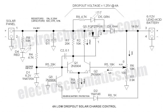
This Low Dropout Voltage (LDO) solar charge controller utilizes a straightforward differential amplifier combined with a series P-channel MOSFET linear regulator, creating an effective synergy. The voltage output is adjustable and is primarily designed for charging 12V lead-acid batteries....
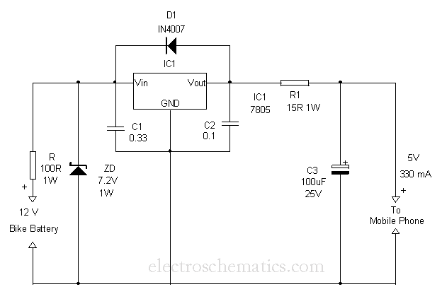
This circuit provides a simple and efficient method to draw current from a motorcycle battery to charge a mobile phone. Most mobile phone battery packs consist of three 1.2-volt cells, resulting in a total voltage of 3.6 volts. For...
During rainy seasons, it can be quite bothersome when the car wipers operate continuously without pause. Have you ever considered implementing speed control for the wipers? While there are wiper control modules available commercially, many of them can be...
This amplifier circuit exhibits a very low power consumption, with a total current draw of 675 nA. The output voltage swing is 300 mV peak-to-peak (pp) with a gain of 20. The amplifier circuit is designed to operate with minimal...
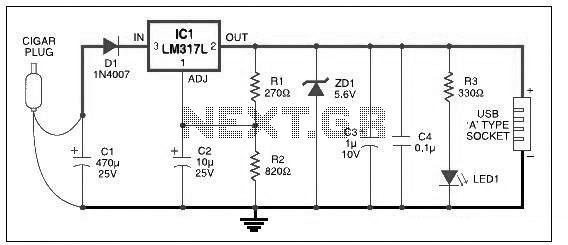
This USB car charger circuit adapter is designed for use with a car's cigarette lighter socket. It functions as a DC-DC power converter, effectively converting the 12V voltage from the car battery into a stable 5V output. This circuit...
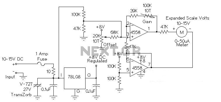
This circuit is used to measure the voltage on a 12V (nominal) lead acid rechargeable battery system. It was specifically designed for use in solar powered systems, but is general enough that it can be used for automotive or...
Warning: include(partials/cookie-banner.php): Failed to open stream: Permission denied in /var/www/html/nextgr/view-circuit.php on line 713
Warning: include(): Failed opening 'partials/cookie-banner.php' for inclusion (include_path='.:/usr/share/php') in /var/www/html/nextgr/view-circuit.php on line 713