
Wireless Sensor Motor Control Circuit
The schematic for the receiver part of this project comprises four main components: the 18F4520 microcontroller, the XBee Maxstream, a power transistor, and an LED bar. The connections among these components are also depicted in the schematic. To simplify power management, an LM317 variable regulator will supply power to the entire project, configured to output +3.3V using a resistor and trimpot setup. This second XBee module will relay received commands to the PIC 18LF4520 for processing. As with the transmitter, a +3.3V PIC is used since the XBee modules cannot function at +5V. The TIP42 power transistor controls the motor's operation, with its base pin connected to the PIC microcontroller's CCP1 pin, which outputs PWM signals. PWM will be utilized to adjust the motor speed, as previously discussed. To provide a visual representation of the current status and speed level (ranging from 0 to 8, where 0 indicates the motor is off and 8 indicates full speed), an LED bar will be connected to the PIC microcontroller's PORTD. This port contains eight digital I/O pins, each controlling an individual LED on the LED bar.
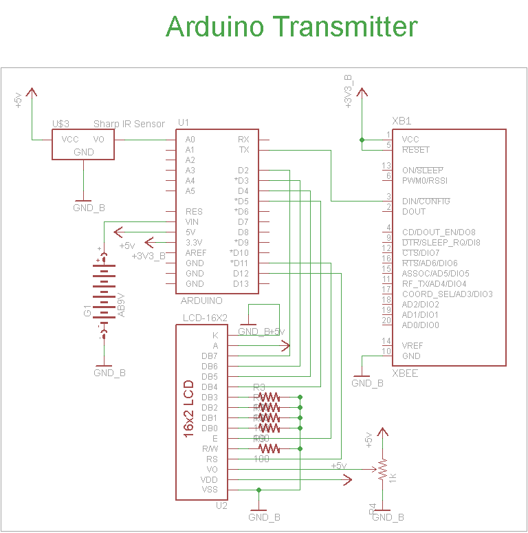
The transmitter section integrates the Arduino UNO, which serves as the central processing unit, processing input from the Sharp IR distance sensor to determine proximity. The XBee wireless modules facilitate communication between the transmitter and receiver sections, ensuring that commands are transmitted effectively. The 16x2 LCD provides real-time feedback to the user, displaying information such as the status of the wireless connection and the operational parameters of the motor.
In the receiver section, the 18F4520 microcontroller processes the commands received from the XBee module. The LM317 regulator ensures that all components receive the appropriate voltage, maintaining system stability. The TIP42 transistor acts as a switch, allowing for precise control of the motor's operation. The PWM signals generated by the PIC microcontroller enable variable speed control, enhancing the system's responsiveness. The LED bar visually indicates the operational status, providing immediate feedback on the motor's speed setting. This comprehensive schematic design effectively integrates all components, ensuring reliable communication and control within the system.The schematic for the transmitter in this project has 4 main parts, the Arduino UNO, the sharp IR distance sensor, the XBee Wireless Modules and the 16x2 LCD. You can see how these parts are connected together to build the system we want in the schematic below: The arduino has on-board power regulators so we don`t have to do anything special b
esides plug in a standard DC power jack, which will be regulated to +5v and +3. 3v. The IR Proximity Sensor has a 3 pin connector that is super simple, Vsupply, Gnd, Vout. Vsupply is connected to +5v power and Gnd to Ground. Vout will be connecting to pin AN0 of the Arduino, this is an analog-to-digital converter pin. This module will be used for transmitting the command from the Arduino UNO to the PIC receiver system. XBee modules run off of +3. 3v so its important not to use a +5v system here! This is a standard 16x2 LCD display that runs off of the hitachi hd44780 command set. It will be used to display output to us so that we know the wireless communication is working and so that we can know what motor speed we`re currently at.
The schematic for receiver part of this project has 4 main parts, the 18F4520 microcontroller, the XBee Maxstream, the power transistor and the LED bar. You can see how these parts are connected together to build the system we want in the schematic below: To make things simple, we`ll use a LM317 variable regulator to supply the power for this entire project.
We will configure it to output +3. 3v with a resistor + trimpot configuration. This is the second XBee module that will be used to passing the received command to the PIC 18LF4520 for processing. Again, we`re using a +3. 3v PIC because the XBee modules cannot operate at +5v power! The TIP42 power transistor allows the motor to be turned off or on. The base pin of the TIP42 is connected to the PIC microcontroller`s CCP1 pin, which is a PWM output pin from the PIC.
PWM will be used to drive the motor at different speeds as we discussed in the theory section. To give a visual read-out of the current status and speed level (level 0 to 8, 0 motor is off, 8 motor is full speed!) we`ll use an LED Bar connected to the PIC microcontroller`s PORTD. This port has 8 digital I/O pins which will each drive a single LED, on the LED Bar. 🔗 External reference
Related Circuits

This is a design for a scoring game circuit suitable for any occasion where dice are used. The circuit utilizes a NE555 timer, a 74LS192 counter, a 74LS247 decoder, and a seven-segment LED display. The timer IC1 generates a...
The circuit is designed for a broadband linear detection application with a bandwidth of 10 MHz. It serves as a millivoltmeter measuring instrument suitable for frequencies exceeding 10 MHz. The circuit features a linear detector utilizing operational amplifiers, specifically...
A simple transformerless power supply circuit with a diagram and schematics that provides a 5 volts DC output. This is a low-cost, low-current power supply circuit suitable for simple applications such as powering an LED. The transformerless power supply circuit...
Fading a video signal cannot be achieved merely by attenuating the composite signal, as the synchronization signal may fall below an unacceptable level. Fading a video signal involves a careful adjustment of both the luminance and chrominance components while...
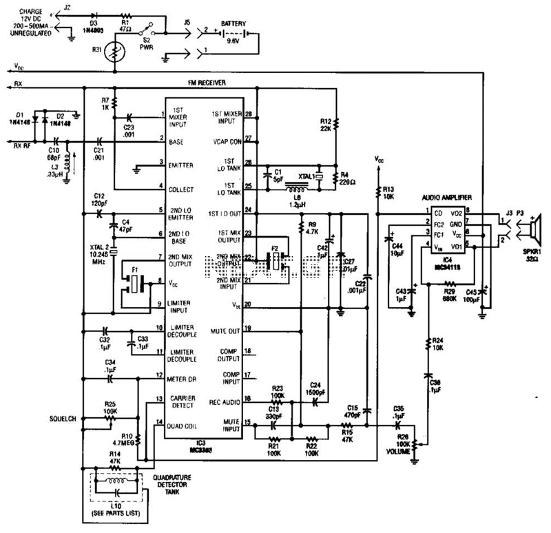
Using a Motorola MC3363 LSI one-chip FM receiver, the circuit is a dual-conversion FM receiver with a 10.7-MHz IF chain. IC4 provides power to drive a small speaker. The described circuit employs the Motorola MC3363 integrated circuit, which is designed...
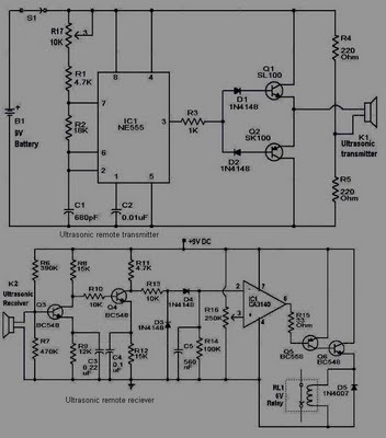
This circuit is straightforward and well-defined. The transmitter operates at 9 volts, while the receiver circuit functions at 5 volts. The transmitter utilizes a 555 timer and two SL100 transistors to perform its function. The receiver incorporates a small...
Warning: include(partials/cookie-banner.php): Failed to open stream: Permission denied in /var/www/html/nextgr/view-circuit.php on line 713
Warning: include(): Failed opening 'partials/cookie-banner.php' for inclusion (include_path='.:/usr/share/php') in /var/www/html/nextgr/view-circuit.php on line 713