


Water sensor alarm
#water sensor
#humidity sensor
#LM1801
#comparator
#alarm circuit
#warning sound
#reference voltage
#threshold detection

Description: This small water sensor alarm circuit produces a loud warning sound when a humidity sensor detects the presence of water. The circuit utilizes the low-power comparator LM1801 from National Semiconductor. The reference voltage for the integrated circuit is established using resistor R2. When the voltage at pin 4 of the LM1801 exceeds a predetermined threshold, the circuit is activated.
The water sensor alarm circuit is designed to provide an effective means of detecting water presence and alerting users through an audible alarm. The core component, the LM1801, serves as a voltage comparator, which continuously monitors the voltage level derived from the humidity sensor. The humidity sensor is typically a resistive or capacitive type that changes its resistance or capacitance based on moisture levels in the environment.
The reference voltage, set by resistor R2, is crucial for determining the sensitivity of the circuit. A lower resistance value will result in a lower reference voltage, making the circuit more sensitive to minor changes in humidity. Conversely, a higher resistance value will increase the reference voltage, requiring a more significant change in humidity to trigger the alarm.
When the humidity sensor detects water, it causes the voltage at pin 4 of the LM1801 to rise above the reference voltage. This condition activates the output pin, which can be connected to a piezoelectric buzzer or an alarm speaker. The alarm will sound loudly, alerting individuals in the vicinity to the presence of water, which could indicate a leak or flooding situation.
Additional components may include a power supply circuit to provide the necessary voltage to the LM1801 and the sensor, as well as bypass capacitors to stabilize the power supply and filter out noise. The circuit should be designed with appropriate safety measures, such as using components rated for the expected environmental conditions, including humidity and temperature variations.
Overall, this water sensor alarm circuit is a practical application of electronic components that provides a reliable warning system for water detection, ensuring timely intervention to prevent potential damage.This small water sensor alarm circuit makes a loud warning sound when a humidity sensor detects a quantity of water. This circuit assembly is an application of low power comparator LM1801 made by National Semiconductor.
The reference voltage for the integrated circuit is fixed with the help of R2.When pin 4 of the LM1801 voltage exceeds preset threshold, bec..
The water sensor alarm circuit is designed to provide an effective means of detecting water presence and alerting users through an audible alarm. The core component, the LM1801, serves as a voltage comparator, which continuously monitors the voltage level derived from the humidity sensor. The humidity sensor is typically a resistive or capacitive type that changes its resistance or capacitance based on moisture levels in the environment.
The reference voltage, set by resistor R2, is crucial for determining the sensitivity of the circuit. A lower resistance value will result in a lower reference voltage, making the circuit more sensitive to minor changes in humidity. Conversely, a higher resistance value will increase the reference voltage, requiring a more significant change in humidity to trigger the alarm.
When the humidity sensor detects water, it causes the voltage at pin 4 of the LM1801 to rise above the reference voltage. This condition activates the output pin, which can be connected to a piezoelectric buzzer or an alarm speaker. The alarm will sound loudly, alerting individuals in the vicinity to the presence of water, which could indicate a leak or flooding situation.
Additional components may include a power supply circuit to provide the necessary voltage to the LM1801 and the sensor, as well as bypass capacitors to stabilize the power supply and filter out noise. The circuit should be designed with appropriate safety measures, such as using components rated for the expected environmental conditions, including humidity and temperature variations.
Overall, this water sensor alarm circuit is a practical application of electronic components that provides a reliable warning system for water detection, ensuring timely intervention to prevent potential damage.This small water sensor alarm circuit makes a loud warning sound when a humidity sensor detects a quantity of water. This circuit assembly is an application of low power comparator LM1801 made by National Semiconductor.
The reference voltage for the integrated circuit is fixed with the help of R2.When pin 4 of the LM1801 voltage exceeds preset threshold, bec..
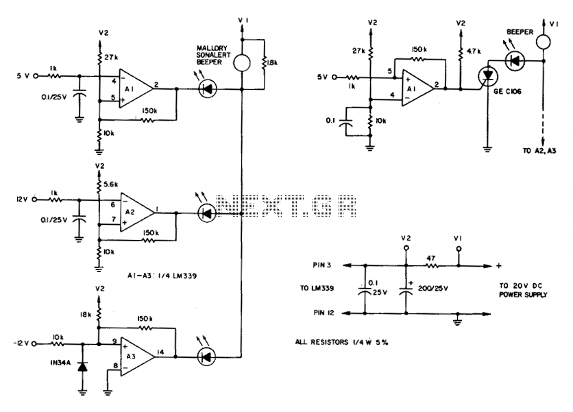
Comparator for over-voltages
To maintain an alarm condition when an overvoltage transient disappears, an SCR should be added to the comparator circuits. For SCR operation, the voltages to the comparator inputs are inverted. The triple-voltage monitoring circuit detects transient power-supply over-voltages. If excessive...
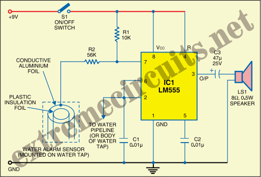
drinking water alarm schematics
The State Jal Boards supply water for a limited duration each day. The timing of the water supply is determined by management, leaving the public unaware of the schedule. In this context, a water alarm circuit can alleviate long wait...
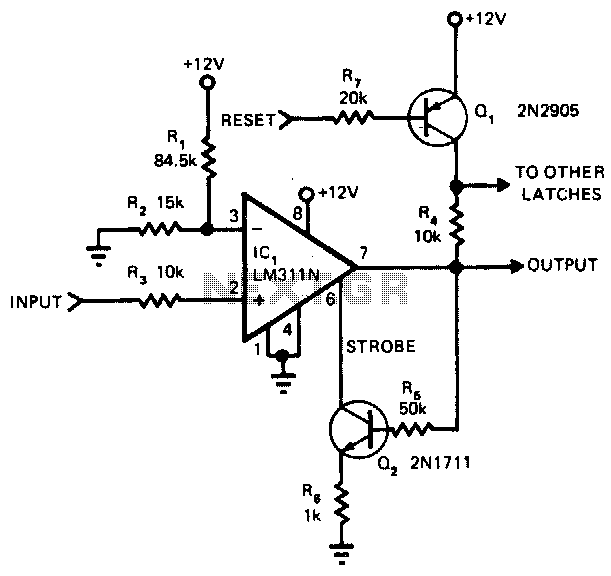
Comparator-latch
The main advantage of this circuit, in comparison to other comparators, is its capability to latch once the input surpasses a specified threshold level. When the input goes beyond this threshold, the output of the LM311N rises. This change activates...
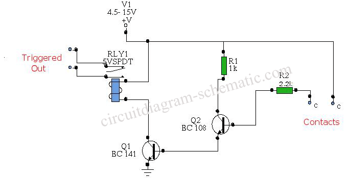
Water Activated Relay circuit board
The circuit diagram represents a water-activated relay circuit. This circuit employs two transistors configured as a high-gain compound pair. The transistors used are 2N2222A for T1 and T2, which may also be substituted with BC108. The current gain is determined...

The reference voltage of the symmetrical bipolar comparator
An AI comparator input is connected to a reference resistor (Rl). When the output reaches a specified level, known as VREP (absolute value), the output also stabilizes at this level. The outputs Ai and As are connected to an OR...
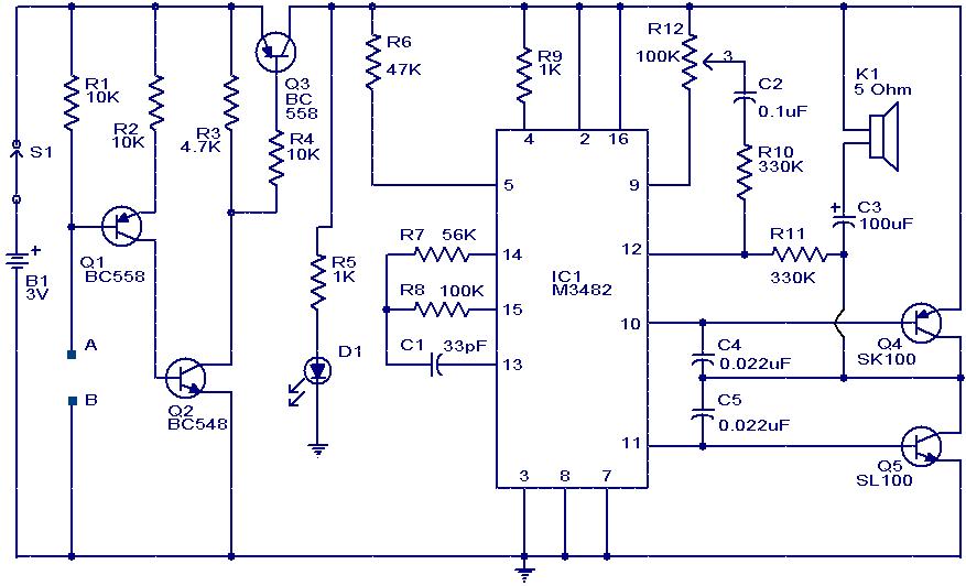
water sensor alarm circuit using ic
This circuit is a simple musical alarm that generates a tone when water or another conductive liquid touches the two sensor wires provided. It utilizes four transistors and a melody generator integrated circuit (IC) M3482. When water bridges the sensor...
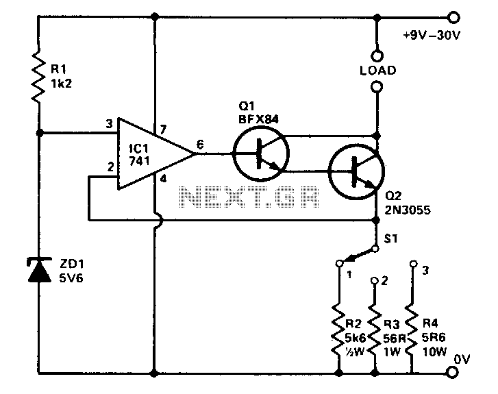
Precision buffered reference
The circuit provides three preset currents that remain constant despite variations in ambient temperature or line voltage. A temperature-stable reference voltage is produced by ZD1 and applied to the non-inverting input of IC1. A 100% feedback is applied from the...
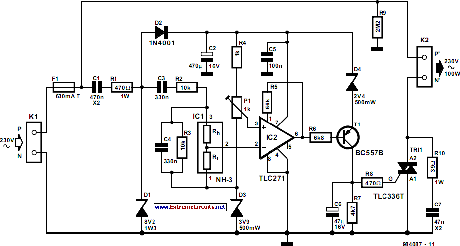
Automatic Air Humidifier
The humidifier circuit is based on a specific humidity sensor, Type NH-3 from Figaro. The circuit controls a ventilator that is part of an air humidifying system, depending on the sensor output. A triac is used to switch the ventilator...
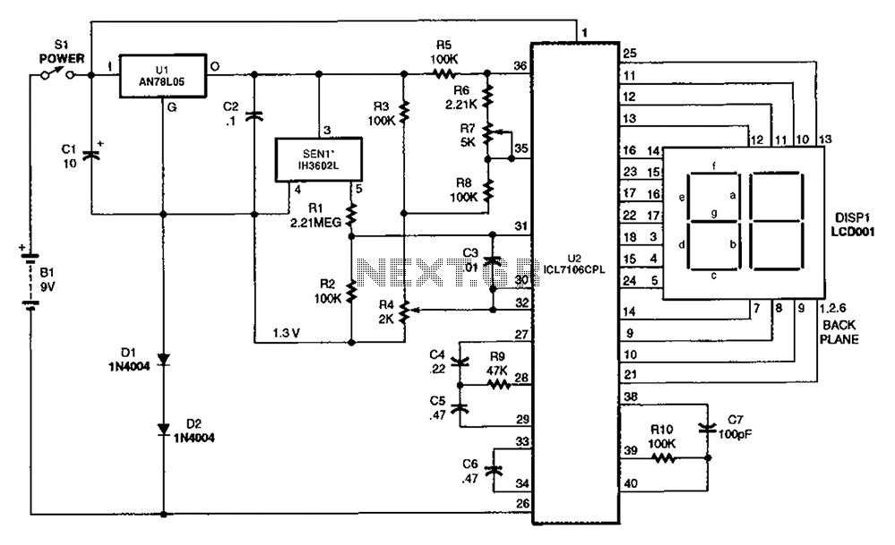
Relative humidity digitizer circuit diagram
The output DC voltage of sensor SEN1 changes linearly in response to variations in relative humidity. This DC voltage is routed through resistors R1 and R2 to the analog-to-digital (A/D) converter chip U2. Resistor R4 is connected to ground, while...