
am radio circuit using transistor

The AM transmitter circuit is designed to operate at a frequency of 3.587 MHz, making it suitable for medium-wave broadcasting. The core of the circuit employs a transistor (T1), which functions as the oscillator and modulator. The use of a ceramic resonator ensures frequency stability and precision, which is crucial for AM transmission. When utilizing resonators of different frequencies, the inductor value in the tank circuit must be recalibrated to maintain the desired resonance.
The modulation process is achieved by injecting an audio signal into the emitter of T1. The inclusion of resistor R4 is essential for biasing, ensuring the transistor operates within its active region. The audio driver transformer facilitates the coupling of the audio signal to the RF circuit, allowing for effective modulation of the carrier wave.
The tank circuit, composed of the inductor and the ceramic resonator, plays a vital role in determining the frequency of oscillation. The gang condenser (C7) allows for fine-tuning of the circuit, enabling the user to adjust the output to the exact resonant frequency for optimal transmission performance.
Following the initial modulation stage, the circuit employs two BF495 transistors (T2 and T3) configured in parallel to amplify the modulated signal. This configuration enhances the overall gain of the transmitter, ensuring that the output signal is strong enough for effective transmission. The output from these transistors is then coupled to the antenna via a 100pF capacitor (C4), which blocks any DC component while allowing the RF signal to pass through.
The design of the circuit permits easy assembly on a general-purpose PCB, making it accessible for hobbyists and engineers alike. The anticipated range of one to two kilometers is suitable for various applications, including personal broadcasting and experimental radio projects. The requirement for a regulated 9-volt power supply ensures consistent performance and reliability, critical for maintaining signal integrity during operation.
In summary, this AM transmitter circuit is a robust solution for medium-wave broadcasting, featuring adjustable frequency capabilities and efficient amplification stages, making it a valuable project for electronics enthusiasts.The circuit for a powerful AM transmitter using ceramic resonator/filter of 3. 587 MHz is presented here. This circuit is based on transistor for the core operation of the circuit. Resonators/filters of other frequencies such as 5. 5 MHz, 7 MHz and 10. 7 MHz may also be used. Use of different frequency filters/resonators will involve corresponding va riation in the value of inductor used in the tank circuit of oscillator connected at the collector of transistor T1. This is the figure of the circuit; The AF input for modulation is inserted in series with emitter of transistor T1 (and resistor R4) using a transistor radio type audio driver transformer as shown in the circuit.
Modulated RF output is developed across the tank circuit which can be tuned to resonance frequency of the filter/resonator with the help of gang condenser C7. The next two stages formed using low-noise RF transistors BF495 are, in fact, connected in parallel for amplification of modulated signal coupled from collector of transistor T1 to bases of transistors T2 and T3.
The combined output from collectors of T2 and T3 is fed to antenna via 100pF capacitor C4. The circuit can be easily assembled on a general-purpose PCB. The range of the transmitter is expected to be one to two kilometers. The circuit requires regulated 9 volt power supply for its operation. Note: Dotted lined indicates additional connection if a 3-pin filter is used in place. 🔗 External reference
Related Circuits

The circuit encompasses a main circuit, a trigger circuit, speed negative feedback, negative feedback differential voltage, a current cut-off circuit, loss of field protection, and other components. Given that the motor power is small (1.1 kW), a single-phase circuit...
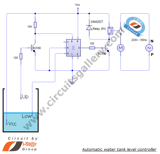
The automatic water level controller circuit is a straightforward engineering project that can automatically switch a domestic water pump on and off based on the water level in a tank. This motor driver circuit can be implemented at home...

Battery vampires are circuits designed to extract as much energy as possible from batteries or cells. They are not regulated drivers; rather, they are boost circuits that create a higher output voltage from a low input voltage and provide...

Implementing peak-detector circuits is straightforward with the CA3130, as illustrated in the schematic diagram of this circuit. The figure below presents the schematic diagram. The CA3130 is a high-performance operational amplifier that is well-suited for peak detection applications due to...

The primary function of the optical receiver is to extract information encoded on a modulated light carrier from a distant transmitter and restore it to its original form. A typical through-the-air communications receiver can be divided into five distinct...
The microphone preamplifier circuit design presented in this schematic utilizes the SSM2015 component manufactured by Precision Monolithics Inc. (PMI). This component provides high amplification with low noise characteristics (1.3nV/f). The design is configured to handle differential input signals and...