
Positive and Negative Peak Detector Circuit Using CA3130 Op-Amp

The CA3130 is a high-performance operational amplifier that is well-suited for peak detection applications due to its high input impedance and low offset voltage. In a typical peak detector circuit, the CA3130 is configured to amplify the input signal, allowing it to detect the peak value effectively.
The circuit generally consists of the CA3130 op-amp, a diode, and a capacitor. The input signal is fed into the non-inverting terminal of the op-amp, while the inverting terminal is connected to a feedback loop that includes the diode and capacitor. The diode allows current to flow only in one direction, charging the capacitor to the peak voltage of the input signal. The capacitor holds this charge, representing the peak value until the input signal drops below this level.
To ensure accurate peak detection, the choice of diode is crucial, as it must have a fast response time and low forward voltage drop. Schottky diodes are often preferred for this application due to their rapid switching capabilities and minimal voltage loss. The capacitor value should be selected based on the expected frequency of the input signal; a larger capacitor will provide a longer hold time for the peak value but may also slow down the response to rapid changes in the input signal.
In summary, the CA3130 peak detector circuit is a simple yet effective design that leverages the properties of the operational amplifier and passive components to accurately capture and hold the peak value of an input signal. The schematic diagram serves as a visual guide to the connections and component values necessary for successful implementation.Implementing peak-detector circuits is very easy with the CA3130, as shown in schematic diagram of this circuit. The figure below shows the schematic diagram of. 🔗 External reference
Related Circuits

Various tools can be utilized with a musical instrument to generate different sound effects, with the simplest being the repetition of tone, often referred to as echo. This equipment enhances the music being played. The circuit diagram is designed...

This design outlines a fire alarm circuit that utilizes a light-dependent resistor (LDR) and a lamp to detect fire. The alarm is activated by sensing the smoke produced during a fire. When smoke is present, it obstructs light from...
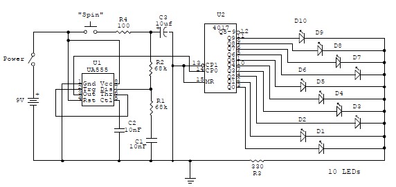
This electronic circuit is a simplified version of an electronic roulette game, utilizing the 4017 integrated circuit (IC), which functions as a 10-stage decade counter/divider. It is driven by a versatile 555 IC configured as a voltage-controlled oscillator (VCO)....

This is a three-band equalizer circuit, specifically a tone control circuit that utilizes a single operational amplifier (op-amp) and features three adjustable frequency ranges: bass, midrange, and treble. The three-band equalizer circuit employs an operational amplifier to achieve tone control...
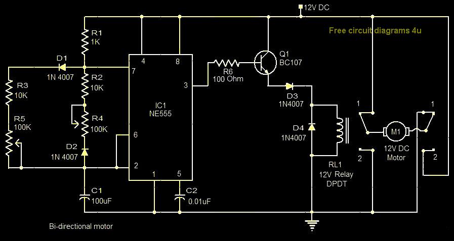
This circuit illustrates a bi-directional motor control circuit utilizing the NE555 integrated circuit (IC). Features include a 12V DC power supply, with the IC employed to control relay RL1. The bi-directional motor control circuit designed with the NE555 IC allows...
This circuit is designed for children's entertainment and can be installed on bicycles, battery-powered cars, motorcycles, as well as on models and various games and toys. When switch SW1 is positioned as depicted in the circuit diagram, it generates...