


MAR-6 VHF-UHF wide band amplifier circuit design electronic project
#MAR-6
#VHF
#UHF
#wide band amplifier
#Mini Circuits
#masthead amplifier
#stable gain
#2GHz
#RF amplifier
#signal output
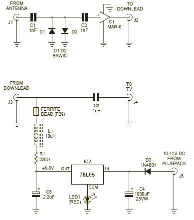
Description: This wideband amplifier circuit is designed using the MAR-6 IC manufactured by Mini Circuits. The MAR-6 VHF-UHF wideband amplifier circuit provides a stable gain of at least 9 dB up to 2 GHz. Since the MAR-6 is designed to receive its power via the signal output pin, it is highly suitable for use as a masthead amplifier. It requires approximately 3.5 V DC at a working current of around 16 mA. The circuit diagram for this masthead amplifier project necessitates only a few external electronic components, allowing for a very compact design when using surface-mounted devices (SMD). With power applied, the LED should glow, and a voltage measurement of approximately 6.8 - 7 V DC should be observed at the end of R1, closer to IC2 and C5. If the LED does not illuminate and there is no voltage reading, it is likely that the DC input has been wired with reverse polarity. If the LED does not light up but nearly the full plug-pack voltage is present at R1, it suggests that the LED may have been connected in reverse.
The MAR-6 wideband amplifier circuit utilizes a single MAR-6 integrated circuit, which is optimized for high-frequency applications. The circuit is configured to amplify signals in the VHF and UHF ranges, making it ideal for applications such as television reception or RF signal processing. The stable gain of at least 9 dB ensures that the signal remains strong even at higher frequencies, thus enhancing the overall performance of the system.
Powering the MAR-6 through the signal output pin allows for a simplified design, eliminating the need for additional power supply circuitry. The operating voltage of approximately 3.5 V DC is low enough to be powered by common battery sources or small power adapters, making it versatile for various applications. The typical current consumption of around 16 mA ensures that the circuit remains energy-efficient.
The inclusion of an LED in the design serves as a power indicator, providing visual feedback when the circuit is operating correctly. The voltage measurement points outlined in the description are crucial for troubleshooting. If the LED fails to illuminate, checking the polarity of the DC input is essential, as incorrect wiring can lead to circuit malfunction. Additionally, ensuring that the LED is connected with the correct polarity is necessary for proper operation.
In summary, this wideband amplifier circuit is characterized by its compact design, efficient power usage, and robust performance across a wide frequency range, making it an excellent choice for applications requiring reliable signal amplification.This wide band amplifier circuit is designed using the MAR-6 IC manufactured by Mini Circuits. This MAR-6 VHF-UHF wide band amplifier circuit will providing stable gain of at least 9dB up to 2GHz. Because the MAR-6 is designed to receive its power via the signal output pin, it`s very suitable for use as a masthead amplifier.
It requires about 3. 5 V DC, at a working current of around 16mA. As you can see in the circuit diagram this masthead amplifier electronic project, require few external electronic parts, so if you will use SMD components you`ll have a very compact design. With power applied, the LED should glow reassuringly and you should be able to measure about 6. 8 - 7V DC at the end of R1 nearer IC2 and C5. If the LED doesn`t glow and you get no voltage reading, chances are that you`ve wired the DC input with reverse polarity.
If the LED doesn`t glow but there`s almost the full plug-pack voltage present at R1, you`ve almost certainly wired the LED in backwards.
The MAR-6 wideband amplifier circuit utilizes a single MAR-6 integrated circuit, which is optimized for high-frequency applications. The circuit is configured to amplify signals in the VHF and UHF ranges, making it ideal for applications such as television reception or RF signal processing. The stable gain of at least 9 dB ensures that the signal remains strong even at higher frequencies, thus enhancing the overall performance of the system.
Powering the MAR-6 through the signal output pin allows for a simplified design, eliminating the need for additional power supply circuitry. The operating voltage of approximately 3.5 V DC is low enough to be powered by common battery sources or small power adapters, making it versatile for various applications. The typical current consumption of around 16 mA ensures that the circuit remains energy-efficient.
The inclusion of an LED in the design serves as a power indicator, providing visual feedback when the circuit is operating correctly. The voltage measurement points outlined in the description are crucial for troubleshooting. If the LED fails to illuminate, checking the polarity of the DC input is essential, as incorrect wiring can lead to circuit malfunction. Additionally, ensuring that the LED is connected with the correct polarity is necessary for proper operation.
In summary, this wideband amplifier circuit is characterized by its compact design, efficient power usage, and robust performance across a wide frequency range, making it an excellent choice for applications requiring reliable signal amplification.This wide band amplifier circuit is designed using the MAR-6 IC manufactured by Mini Circuits. This MAR-6 VHF-UHF wide band amplifier circuit will providing stable gain of at least 9dB up to 2GHz. Because the MAR-6 is designed to receive its power via the signal output pin, it`s very suitable for use as a masthead amplifier.
It requires about 3. 5 V DC, at a working current of around 16mA. As you can see in the circuit diagram this masthead amplifier electronic project, require few external electronic parts, so if you will use SMD components you`ll have a very compact design. With power applied, the LED should glow reassuringly and you should be able to measure about 6. 8 - 7V DC at the end of R1 nearer IC2 and C5. If the LED doesn`t glow and you get no voltage reading, chances are that you`ve wired the DC input with reverse polarity.
If the LED doesn`t glow but there`s almost the full plug-pack voltage present at R1, you`ve almost certainly wired the LED in backwards.
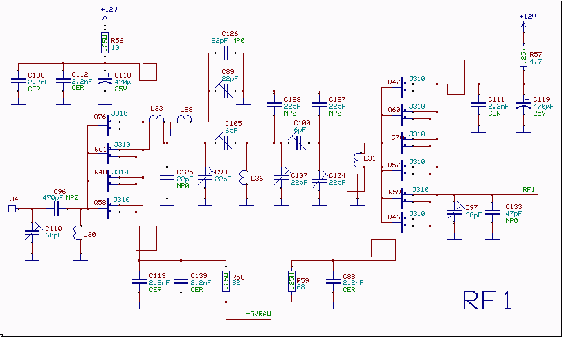
RF amplifier and filter for 144 MHz
The RF amplifiers utilize noiseless feedback through the drain-gate capacitance, incorporating an inductor in the source lead to achieve the necessary 90-degree phase shift between the gate voltage and channel current. The first RF amplifier provides approximately 4 dB of...
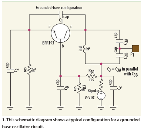
large signal approach yields low noise vhfuhf oscillators
Unlike conventional small-signal methods, employing large-signal, time-domain design techniques facilitates the development of low-noise grounded-base oscillators suitable for VHF/UHF applications.
The implementation of large-signal, time-domain design techniques in the creation of grounded-base oscillators represents a significant advancement in the field of...
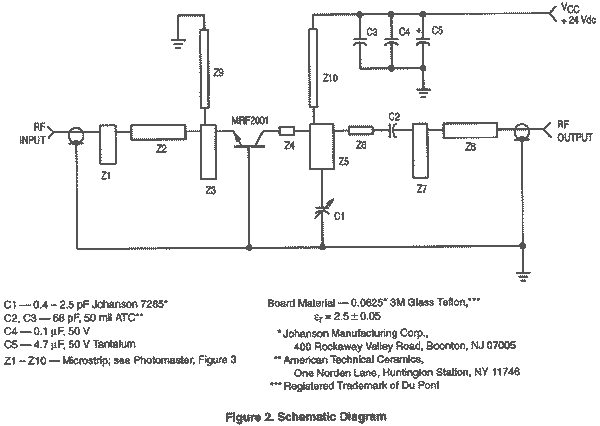
1 Watt 2.3 GHz RF Amplifier Using a MRF2001
This is an image Schematic. No Description available.
The provided input indicates the existence of a schematic image without further descriptive content. In the context of electronic schematics, such images typically represent the arrangement and interconnection of various electronic components,...
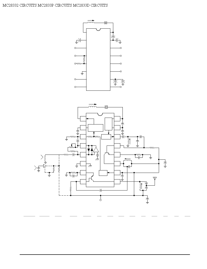
MC28332 Single Chip VHF Narrowband FM Transmitter Application Circuit
Crystal X1 operates in fundamental mode and is calibrated for parallel resonance with a load capacitance of 32 pF. The final output frequency is produced through frequency multiplication within the MC2833 integrated circuit (IC). The RF output buffer at Pin...
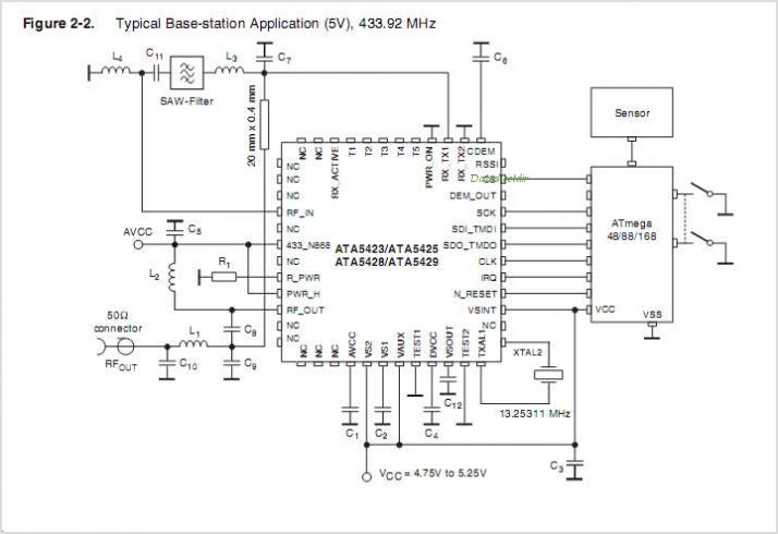
ATA5423 ATA5423 UHF Transceiver For ASK And FSK Systems 315 MHz
The ATA5743 is a multi-chip PLL receiver device housed in an SSO20 package. It has been specifically designed to meet the requirements of low-cost RF data transmission systems, supporting data rates ranging from 1 kBaud to 10 kBaud using Manchester...
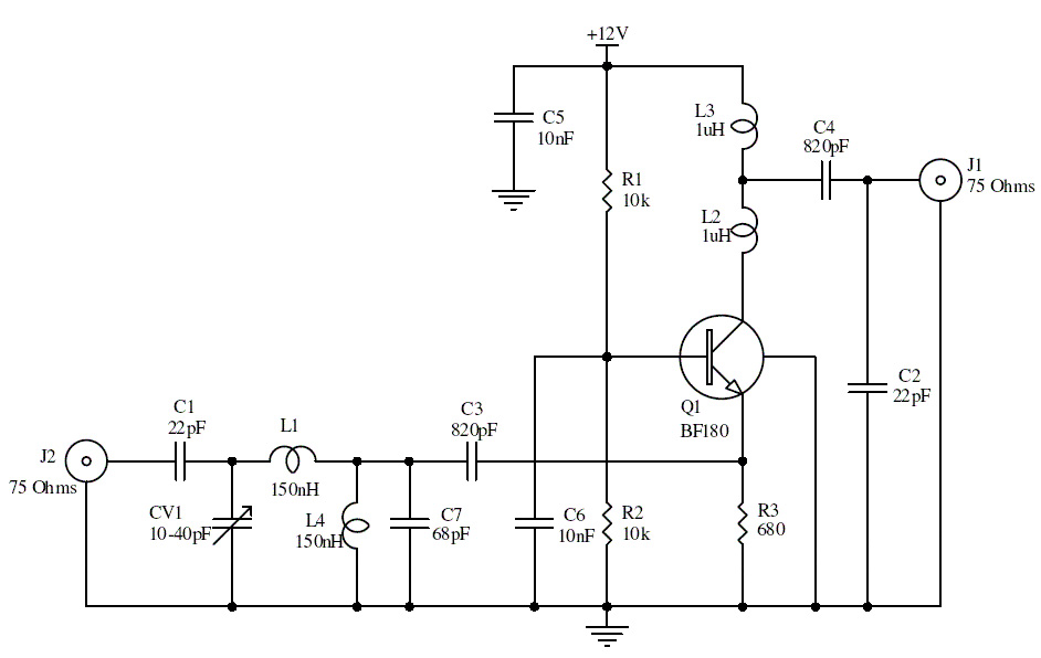
15db uhf tv antenna booster
This is a UHF band TV antenna preamplifier circuit with a gain of 15 dB. It is designed using the BF180 UHF transistor. The input stage consists of a band-pass filter implemented with components C1, CV1, L1, L4, C7, and...

Single-device 80 w 50 ohm vhf amplifier
The amplifier utilizes a single MRF245 transistor and delivers 80 W of output power with a gain of 9.4 dB across the frequency range of 143 to 156 MHz.
The circuit design for the amplifier featuring the MRF245 transistor is intended...
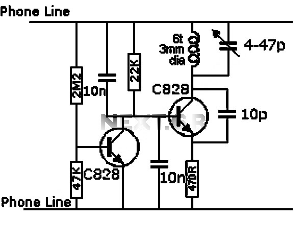
am rf amp for internal antenna circuit
Any NPN transistor can be used. The author used a 2N3904, but a 2N2222A should work just as well. A good, low noise transistor would be even better. Some radios only have three connections to their ferrite bar antenna: the...
1W Linear FM Booster
That RF Amplifier is for boosting small fm transmitters and bugs. It uses two Philips 2N4427 and its power is about 1 Watt. At the output, you can drive any linear with BGY133 or BLY87 and so on. Its power...