
and filter 1 3 5w power rf amplifier

The RF amplifier circuit described is designed to boost the transmission power of FM signals, making it particularly useful for amateur radio enthusiasts. The BLY90 transistor, selected for its favorable gain characteristics, plays a critical role in the amplification process. With a gain of 5dB, it effectively amplifies the input signal from the transmitter, enhancing the output power significantly.
The circuit operates within the FM frequency range of 88-108 MHz, which is the standard band for FM broadcasting. The input stage of the amplifier accepts a signal from an existing transmitter, which typically outputs between 15-20W. This input signal is fed into the amplifier, where it is processed and amplified to a level of 50-60W.
For optimal performance, the output of the amplifier must be connected to either a dummy load or an antenna. A dummy load is often used during testing to prevent signal radiation and ensure that the amplifier operates correctly without broadcasting. If connecting to an antenna, a standing wave bridge should be utilized to match the impedance and minimize signal reflections, which can lead to inefficiencies and potential damage to the circuit.
Powering the amplifier requires a DC supply voltage in the range of 11-15V, with a current capacity of 4-5A. This specification is crucial for ensuring that the amplifier operates within its designed parameters without overheating or failing due to insufficient power.
The tuning of the amplifier is facilitated by four variable capacitors (C1-C4), which allow for fine adjustments to be made. By carefully tuning these capacitors, users can optimize the output power and ensure that the amplifier is functioning at peak efficiency. Once the adjustments are complete and the maximum output power is achieved, the amplifier is ready for deployment in an FM transmission application.
This RF amplifier circuit represents a valuable tool for amateur radio operators seeking to increase their transmission capabilities, providing a practical solution for enhancing signal strength and coverage.A amplifier of force RF for the FM, is always essential for the amateur that wants it strengthens some small transmitter, that likely already it has manufactured or has been supplied ready. The present circuit can give 50-60W RF force of expense, with control smaller than 15-20W in the region of frequencies of FM, that is to say in the 88-108MHZ.
Transistor that we selected for this manufacture is the BLY90, that has gain 5dB. If all they are it includes, you connect the exit of your transmitter (15-20W) in input the amplifier. The exit of amplifier him you will connect in some charge (dummy load) or in the aerial, through bridge stagnant waves.
Supply with tendency 11-15V your amplifier (power supply it should gives current 4-5A). Regulate the 4 variable C1-C4, until you take the biggest force of expense. The amplifier is ready. 🔗 External reference
Related Circuits
The circuit is based on application of National Semiconductor. First is constituted by three voltage regulators LM338 [IC1-2-3] connected in parallel. The each one regulator has the possibility of giving 5 A in his output. Also exists the possibility...

The circuit was designed based on the functionality of a Class A amplifier to create a headphone circuit. A BC308 epitaxial planar PNP transistor is utilized. The Class A amplifier configuration is known for its linearity and low distortion, making...
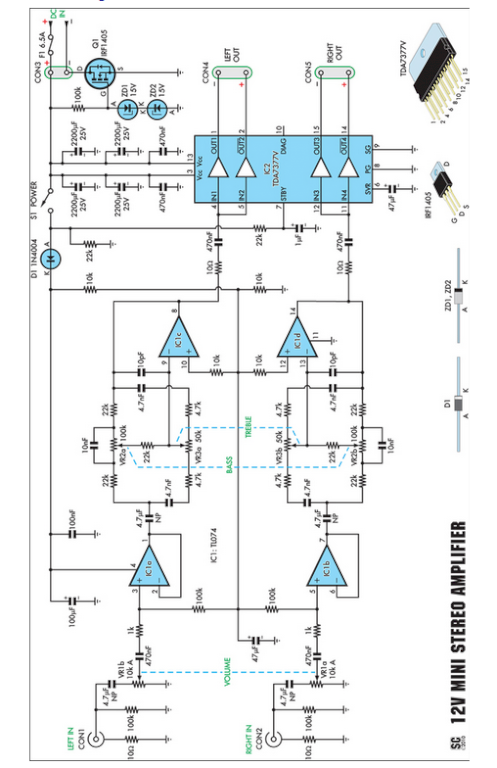
Amplifiers that operate on 12V DC typically do not deliver significant power and are often not classified as high-fidelity (hifi) devices. However, this compact stereo amplifier meets the power requirements effectively. This compact stereo amplifier is designed to operate efficiently...

A mobile phone charger powered by a solar cell power supply is described. This system utilizes a dual comparator circuit that connects the solar panel to the battery when the voltage at the battery terminal is low and disconnects...

UART, GPS. This application note illustrates how to integrate a GPS module SC16C2552B into a navigation system using a Philips UART. With the rapid advancement of GPS (Global Positioning System) technologies, GPS is being increasingly utilized across various sectors....

This is a simple non-contact AC power monitor designed for home appliances and laboratory equipment that should remain continuously powered. A failure of the fuse or a power outage in the equipment can lead to significant damage if unnoticed....