
arduino uno schematic
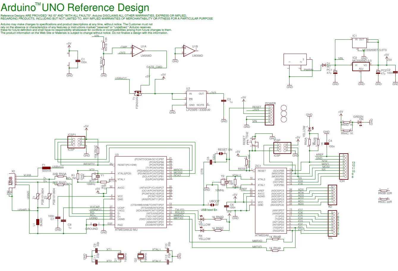
The Arduino Uno microcontroller board, based on the ATmega328, serves as a versatile platform for a wide range of electronic projects. The board's 14 digital I/O pins allow for extensive interfacing with various components, while the 6 analog inputs facilitate the connection of sensors and other analog devices. The inclusion of a 16 MHz crystal oscillator ensures stable operation and timing accuracy, which is critical for real-time applications. The USB connection allows for easy programming and communication with a computer, while the power jack provides an alternative power supply option, enhancing the board's flexibility in different environments.
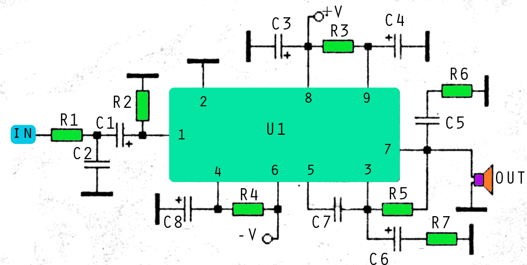
The 800-watt audio amplifier schematic showcases a robust design utilizing MOSFETs, which are known for their efficiency and ability to handle high power levels. This amplifier is designed to deliver exceptional sound quality with low distortion, making it ideal for applications such as sub-woofer amplification or high-powered surround sound systems. The schematic likely includes key components such as the input stage, output stage, power supply circuitry, and feedback mechanisms to optimize performance.
The A/B Box pedal schematic, designed by Rick Barker, represents a practical solution for musicians needing to switch between different audio sources. The low-noise dual preamp enhances the signal integrity, ensuring that the sound quality remains high when switching between microphones or instruments. This pedal design is particularly beneficial for harmonica players but can be adapted for various applications in electric guitar setups. The schematic may include details on the input/output jacks, switching mechanism, and power supply requirements, providing a comprehensive guide for construction and use.
Overall, these schematics represent significant contributions to the fields of microcontroller applications and audio amplification, showcasing the versatility and capability of modern electronic design.Here the Arduino UNO schematic diagram (click to enlarge): About Arduino UNO: The Arduino Uno is really a microcontroller board based on the ATmega328. It has 14 digital input/output pins (of which 6 may be employed as PWM outputs), 6 analog inputs, a 16 MHz crystal oscillator, a USB connection, a power jack, an ICSP.
Here the schematic diagram o f 800 watt audio amplifier with MOSFET. This amplifier can be used for practically any application that requires high power, low noise, distortion and excellent sound. Examples would be Sub-woofer amp, FOH stage amplifier, One channel of a very high-powered surround sound amplifier etc.
For detail explanation about how this circuit. This is a A/B Box pedal schematic for electric guitar was designed by Rick Barker. This A/B Box effect was originally designed for switching between different harmonica mics. This A/B Box featured low noise dual preamp for better effect. Download the schematic of A/B Box Guitar Effect: Download Link 🔗 External reference
Related Circuits
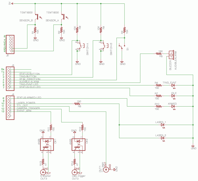
The core of the circuit features an Arduino microprocessor, represented by the header pins on the left side of the circuit schematic. Two analog inputs, labeled 0 and 1, are connected to the emitter sides of TEMT6000 ambient light...
This amplifier circuit utilizes three voltage levels: positive, negative, and ground, with a maximum voltage of approximately 55V DC. The circuit can accommodate several integrated circuits (ICs), including STK 030, 058, 075, 077, 078, 080, 082, 083, 084, and...

The following diagram illustrates a four-band blaster circuit. This blaster is utilized to enhance sound fidelity, emphasize specific instruments, eliminate unwanted noise, or create entirely new and distinct timbres. The four-band blaster circuit is designed to manipulate audio signals across...
This device transmits data regarding the state of an office to Twitter, as it is deemed slightly more relevant than sharing similar information about a residence. It holds potential significance for biodiversity-related activities, especially when integrated with long-range WiFi...
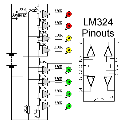
This circuit utilizes two quad op-amps to create an eight LED audio level meter. The op-amp employed in this circuit is the LM324, a widely used integrated circuit that is readily available from numerous electronic component suppliers. The 1K...
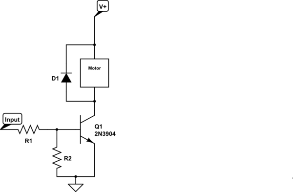
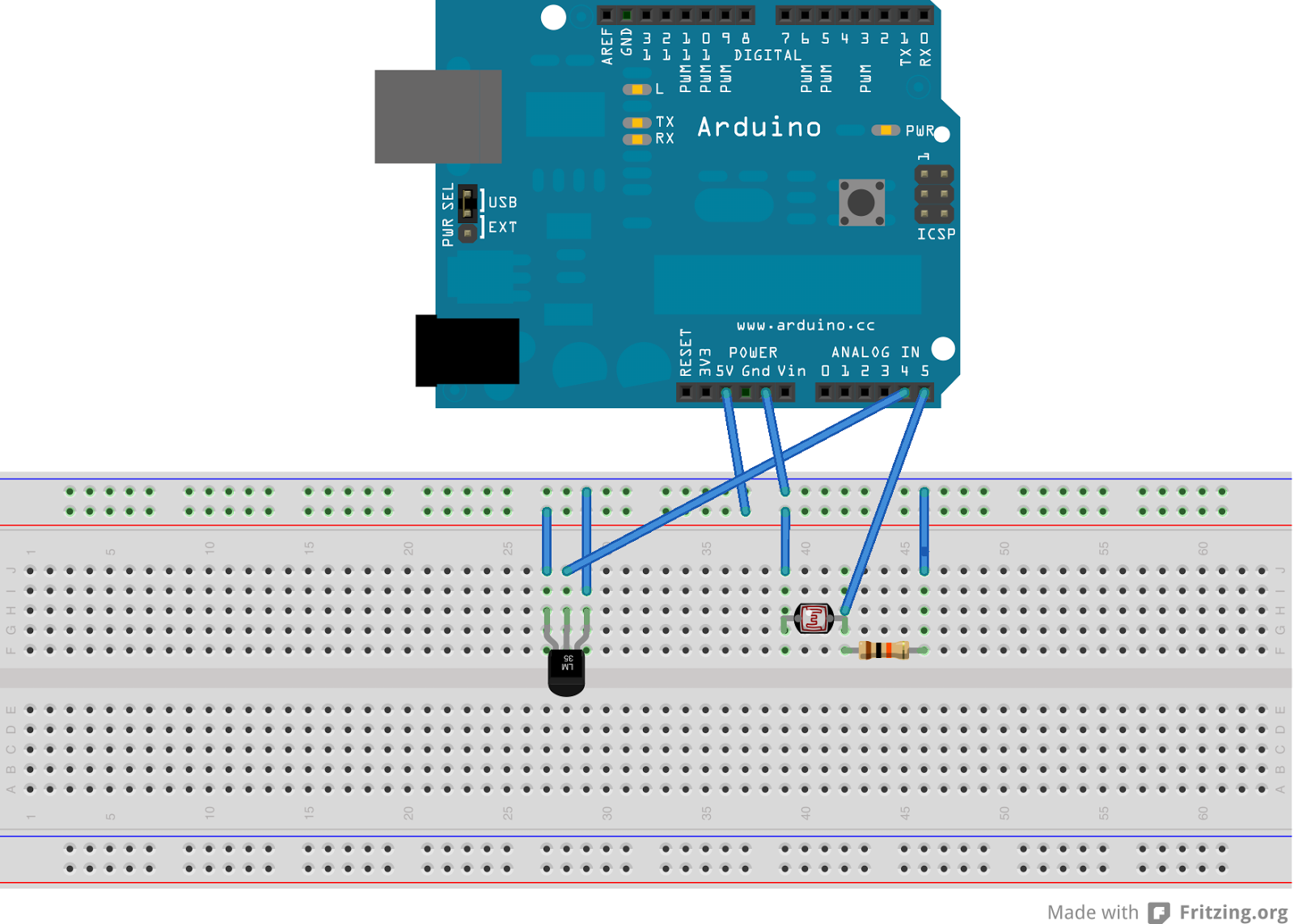
Control a small 5V motor using an external power supply by triggering a transistor with an Arduino. The transistor in use is an NPN type, specifically the 2N3904. To control a small 5V motor using an Arduino and an NPN...