
4 Band Equalizer schematic diagram
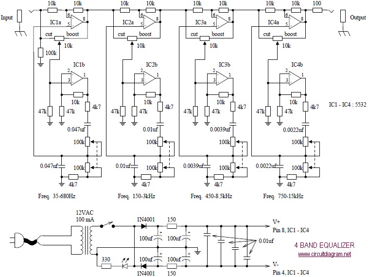
The four-band blaster circuit is designed to manipulate audio signals across four distinct frequency bands. Typically, these bands are categorized into low, mid-low, mid-high, and high frequencies. Each band is processed through a separate equalization stage, allowing for precise control over the amplitude and tonal characteristics of the audio signal.
The circuit generally consists of the following key components:
1. **Input Stage**: This stage receives the audio signal, which can come from various sources such as musical instruments or microphones. It often includes a buffer amplifier to ensure that the input impedance is high enough to prevent signal loss.
2. **Equalization Stages**: Each of the four bands is processed through its own equalizer, which may utilize active or passive components. Active equalizers typically use operational amplifiers (op-amps) to achieve greater control over the gain and bandwidth of each band. The design may include adjustable potentiometers for tuning the gain of each band, allowing users to tailor the sound to their preferences.
3. **Mixing Stage**: After processing, the signals from each band are mixed together. This stage may include additional circuitry to maintain a balanced output level and to prevent distortion.
4. **Output Stage**: The final output stage may include a power amplifier or a simple buffer to drive the output signal to the desired load, such as speakers or recording equipment. This stage ensures that the output maintains fidelity and clarity, preserving the enhancements made during processing.
The four-band blaster circuit is particularly useful in live sound applications and studio settings, where control over frequency response is crucial for achieving high-quality sound. By effectively managing the tonal balance, it allows sound engineers and musicians to craft their desired audio experience, whether for live performances or recorded tracks.The afterward diagram is the four bandage blaster circuit. Blaster is about acclimated to advance the allegiance of sound, to accent assertive instruments, to abolish causeless noises, or to actualize absolutely new and altered timbres 🔗 External reference
Related Circuits

The third Eagle layout of the program counter has been completed, presenting a clearer design compared to the previous iterations, which were cluttered with intersecting wires, making it difficult to discern connections. This diagram is intended to facilitate understanding...
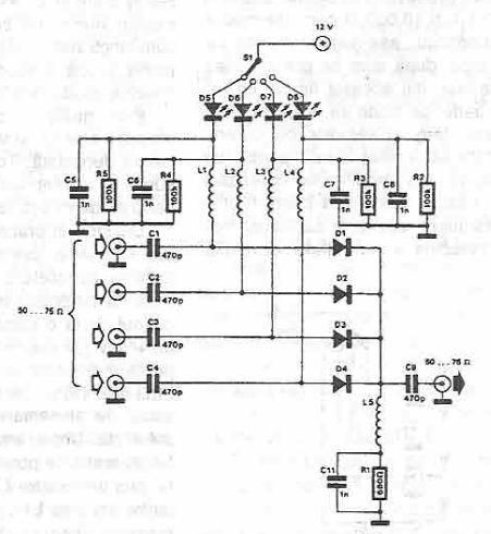
This antenna selector circuit diagram utilizes PIN diodes, which address the drawbacks of mechanical switches, particularly in high-frequency current applications. PIN diodes are well-suited for this purpose due to their linear resistance characteristics across a wide range of current...
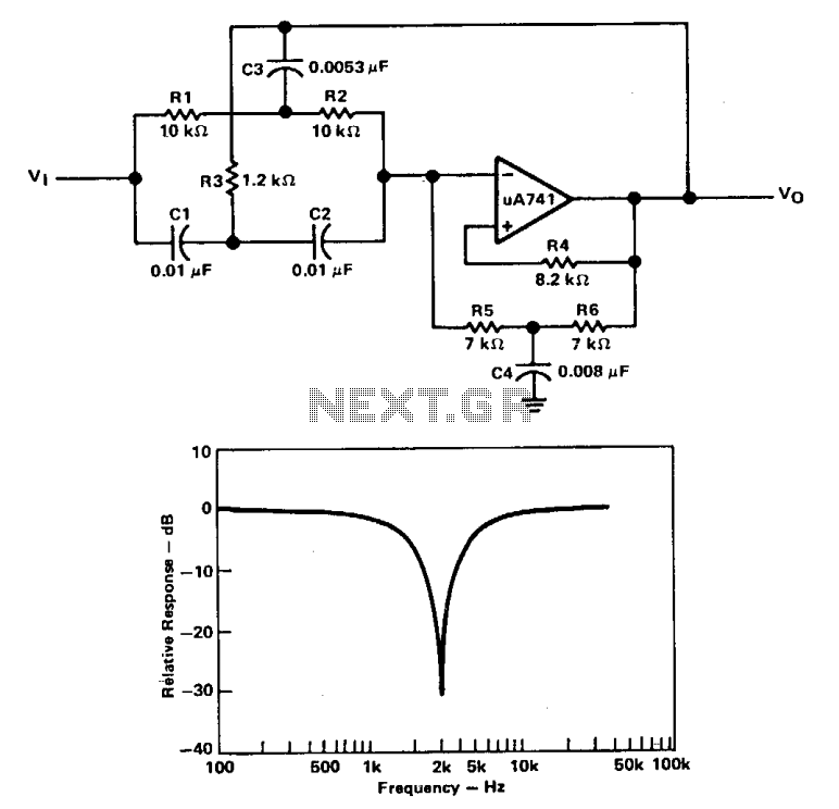
A filter with a band-reject characteristic is commonly known as a notch filter. A typical circuit employing a µ741 operational amplifier is shown in a unity-gain configuration for this type of active filter. The filter response curve illustrated represents...
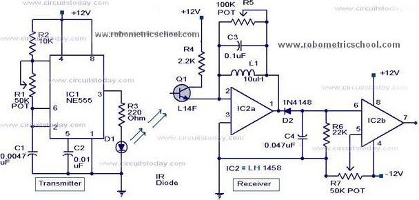
All components used in the Moving Sensor/Detector Schematic Diagram utilize the IC NE555 and the Phototransistor L14F. The primary component in this circuit is the IC NE555, along with an IR LED, the Phototransistor L14F, and the IC LM1458....
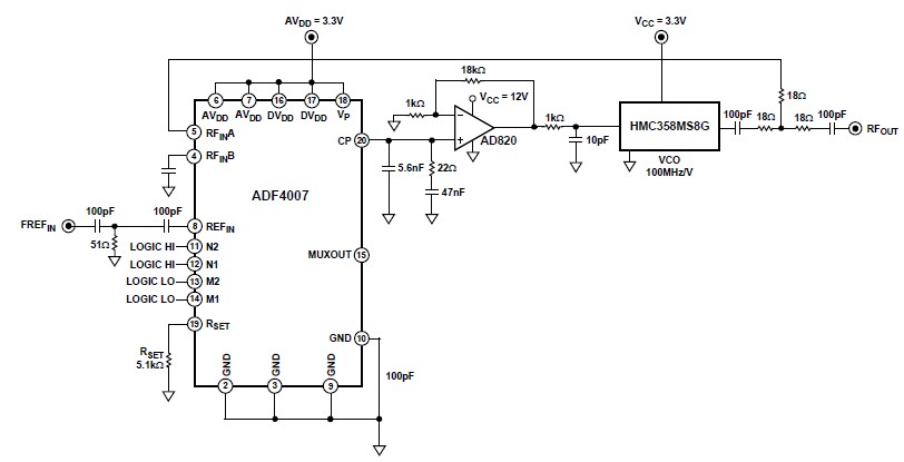
The ADF4007 high-frequency divider Phase-Locked Loop (PLL) synthesizer can be utilized in a variety of communication applications. It operates up to 7.5 GHz on the RF side and 120 MHz at the Phase Frequency Detector (PFD). The device includes...
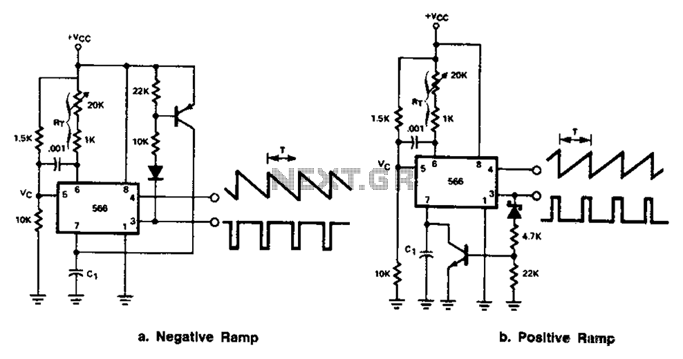
The 566 can be connected to either a positive or negative ramp generator. For a positive ramp generator, an external transistor is driven by the output pin 3. At the end of charging, C1 discharges quickly, allowing for immediate...