


audio-video modulator circuit
#audio modulation
#video modulation
#UHF signal
#TV signal
#video amplifier
#signal conversion
#audio-video processing
#broadcast
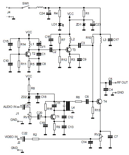
Description: The circuit converts audio and video signals into a UHF TV signal, allowing a video signal from a camera or other source to be connected to a standard TV set. The audio and video signals are transformed into a UHF TV signal. This is a schematic diagram of a video amplifier circuit, built using the high-speed operational amplifier IC LH0032. The parts list includes: R1 = 15KΩ, R2, R3, R4 = 10KΩ, R5, R6, R7, R8, R9 = 1KΩ, R10 = 820Ω, R11 = 1MΩ, R12 = 100Ω (trimmer), R13, R14, R15 = 47Ω, R14 = 10KΩ, C1 = 10µF 63V MKT, C2, C3, C4 = 100nF/63V, C3 = 4.7pF. This is the circuit diagram of a laser communication system that transmits sound or music signals via a laser beam. The intensity of the laser beam varies with the amplitude of the sound signal, and this variation is converted into a corresponding change in voltage level. The following diagram presents the schematic of an Active Tone Control circuit, commonly referred to as "ACTOR." The Active Tone Control circuit enhances the loudness (bass and treble audio signals) using the Baxandall system. This circuit does not utilize a passive configuration. Additionally, this is the circuit diagram of a UHF band TV antenna booster with a 15dB gain. This low-cost antenna booster is straightforward and easy to construct, based on the BF180 UHF transistor. The first stage consists of a band-pass filter formed by components C1, CV1, L1, L4, C7, and C3. The second stage of the circuit is a turbo bass circuit designed to amplify low-frequency sound signals (bass) in an audio system. This active circuit strengthens the incoming audio signal through the first operational amplifier, followed by a second operational amplifier that filters the output.
The circuit designed for converting audio and video signals into a UHF TV signal serves a crucial function in enabling the connection of various video sources, such as cameras, to standard television sets. The use of the LH0032 operational amplifier in the video amplifier circuit ensures high-speed processing of the signals, which is essential for maintaining signal integrity and quality during transmission.
The components listed in the parts list are selected to optimize performance and reliability. Resistors R1 through R15 provide necessary impedance matching and signal conditioning, while capacitors C1 to C4 are employed for coupling and filtering purposes. The choice of a 10µF capacitor for C1 aids in blocking DC components while allowing AC signals to pass through, ensuring that only the desired audio and video signals are amplified.
In the laser communication system, the modulation of the laser beam's intensity in accordance with the audio signal enables wireless transmission of sound. This method is advantageous for applications requiring secure and interference-free communication. The conversion of laser intensity variations into voltage changes is critical for accurate signal reception.
The Active Tone Control circuit, or ACTOR, utilizes the Baxandall tone control system to enhance audio playback quality. By actively boosting bass and treble frequencies, this circuit allows users to customize their audio experience, making it suitable for various listening environments and preferences.
The UHF band TV antenna booster circuit is designed to improve the reception of UHF signals, particularly in areas with weak signal strength. The band-pass filter formed by the specified components ensures that only the desired frequency range is amplified, while unwanted signals are attenuated. This results in clearer and more reliable television reception.
Lastly, the turbo bass circuit effectively enhances low-frequency audio signals, making it an excellent addition to audio systems that require improved bass response. The use of operational amplifiers in this design allows for precise control over the amplification process, ensuring that the output maintains fidelity to the original audio source. Overall, these circuits represent a diverse range of applications in audio and video signal processing, showcasing the versatility and effectiveness of modern electronic design.The circuit will convert an audio and video signal into a UHF TV signal. It`s desired to connect a video signal originating from a camera or other video source to a normal TV set. The audio and video signal is converted into a UHF TV signal so. This is schematic diagram of a video amplifier ci rcuit, built based very high speed opamp IC LH0032. Parts List: R1 = 15K ©+15K © R2-3-4 = 10K © R5, R6, R7, R8, R9 = 1K © R10 = 820 © R11 = 1M © R12 = 100 © trimmer R13, R14, R15 = 47 © R14 = 10K © C1 = 10uF 63V MKT C2, C3, C4 = 100nF/63V C3 = 4. 7pF. This is the circuit diagram of laser communication system that transmit the sound or music signals by way of a laser beam.
The intensity of the laser beam varies together with the amplitude of the sound signal. The variation within the intensity of the laser beam is converted into a variation in the voltage level. The following diagram is the schematic diagram of Active Tone Control circuit, or we often call thic circuit as "ACTOR" Active Tone Control or ACTOR is a electronic audio circuit that serves to increase the Loudness (Bass and Treble audio signal) is active because it uses the Baxandall system.
This circuit does not use a. This is the circuit diagram of UHF band TV antenna booster with 15dB gain power. This low cost antenna booster is simple and easy to build. This circuit formed based on BF180 UHF Transistor. The first stage is an band pass filter constructed by the C1, CV1, L1, L4, C7 and C3, the second stage. This circuit is a circuit of the turbo bass that can be used to multiply the low frequency sound signals (bass) on your audio system.
This circuit is an active circuit in which the incoming audio signal from the input will be strengthened in the first op-amp. The second op-amp that will filter out the.
The circuit designed for converting audio and video signals into a UHF TV signal serves a crucial function in enabling the connection of various video sources, such as cameras, to standard television sets. The use of the LH0032 operational amplifier in the video amplifier circuit ensures high-speed processing of the signals, which is essential for maintaining signal integrity and quality during transmission.
The components listed in the parts list are selected to optimize performance and reliability. Resistors R1 through R15 provide necessary impedance matching and signal conditioning, while capacitors C1 to C4 are employed for coupling and filtering purposes. The choice of a 10µF capacitor for C1 aids in blocking DC components while allowing AC signals to pass through, ensuring that only the desired audio and video signals are amplified.
In the laser communication system, the modulation of the laser beam's intensity in accordance with the audio signal enables wireless transmission of sound. This method is advantageous for applications requiring secure and interference-free communication. The conversion of laser intensity variations into voltage changes is critical for accurate signal reception.
The Active Tone Control circuit, or ACTOR, utilizes the Baxandall tone control system to enhance audio playback quality. By actively boosting bass and treble frequencies, this circuit allows users to customize their audio experience, making it suitable for various listening environments and preferences.
The UHF band TV antenna booster circuit is designed to improve the reception of UHF signals, particularly in areas with weak signal strength. The band-pass filter formed by the specified components ensures that only the desired frequency range is amplified, while unwanted signals are attenuated. This results in clearer and more reliable television reception.
Lastly, the turbo bass circuit effectively enhances low-frequency audio signals, making it an excellent addition to audio systems that require improved bass response. The use of operational amplifiers in this design allows for precise control over the amplification process, ensuring that the output maintains fidelity to the original audio source. Overall, these circuits represent a diverse range of applications in audio and video signal processing, showcasing the versatility and effectiveness of modern electronic design.The circuit will convert an audio and video signal into a UHF TV signal. It`s desired to connect a video signal originating from a camera or other video source to a normal TV set. The audio and video signal is converted into a UHF TV signal so. This is schematic diagram of a video amplifier ci rcuit, built based very high speed opamp IC LH0032. Parts List: R1 = 15K ©+15K © R2-3-4 = 10K © R5, R6, R7, R8, R9 = 1K © R10 = 820 © R11 = 1M © R12 = 100 © trimmer R13, R14, R15 = 47 © R14 = 10K © C1 = 10uF 63V MKT C2, C3, C4 = 100nF/63V C3 = 4. 7pF. This is the circuit diagram of laser communication system that transmit the sound or music signals by way of a laser beam.
The intensity of the laser beam varies together with the amplitude of the sound signal. The variation within the intensity of the laser beam is converted into a variation in the voltage level. The following diagram is the schematic diagram of Active Tone Control circuit, or we often call thic circuit as "ACTOR" Active Tone Control or ACTOR is a electronic audio circuit that serves to increase the Loudness (Bass and Treble audio signal) is active because it uses the Baxandall system.
This circuit does not use a. This is the circuit diagram of UHF band TV antenna booster with 15dB gain power. This low cost antenna booster is simple and easy to build. This circuit formed based on BF180 UHF Transistor. The first stage is an band pass filter constructed by the C1, CV1, L1, L4, C7 and C3, the second stage. This circuit is a circuit of the turbo bass that can be used to multiply the low frequency sound signals (bass) on your audio system.
This circuit is an active circuit in which the incoming audio signal from the input will be strengthened in the first op-amp. The second op-amp that will filter out the.
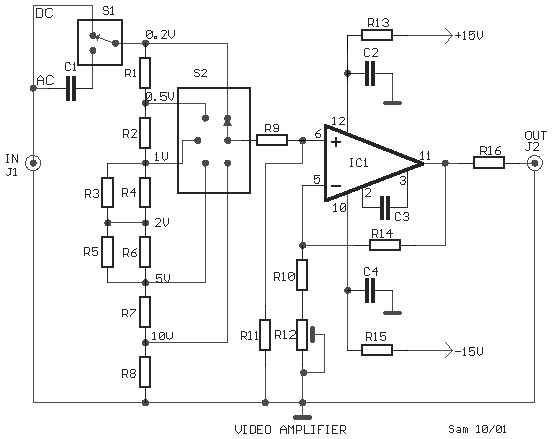
video amplifier circuit
This is a schematic diagram of a video amplifier circuit, built using the very high-speed operational amplifier IC LH0032. Parts List: R1 = 15KΩ, R2, R3, R4 = 10KΩ, R5, R6, R7, R8, R9 = 1KΩ, R10 = 820Ω, R11...
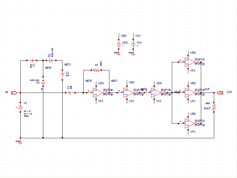
Sine to Square Wave Converter
This schematic example demonstrates a sinusoidal voltage input at a frequency of 10 kHz, which is converted to a square wave using an inverter-based circuit. The VDD and VSS rails are connected to +1V and -1V, respectively. The control file...

1-2Mhz broadcast transmitter
T1 is a low impedance output transformer with a conversion ratio of 5000 to 8 ohms.
The low impedance output transformer, T1, is designed to match the output of an audio amplifier to the impedance of the speaker load. The specified...
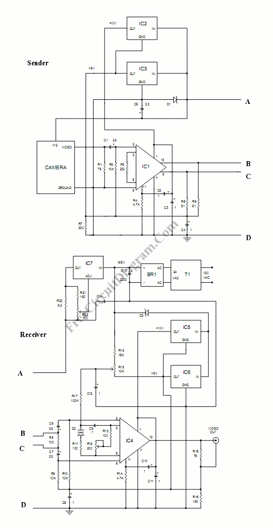
Video Wire: Enable Video Transmission Via Long Cables
This circuit allows for the connection of a camera using a very long wire. The circuit functions as a video amplifier. At the sending end, the amplifier is utilized to.
The circuit described is designed to facilitate the transmission of video...
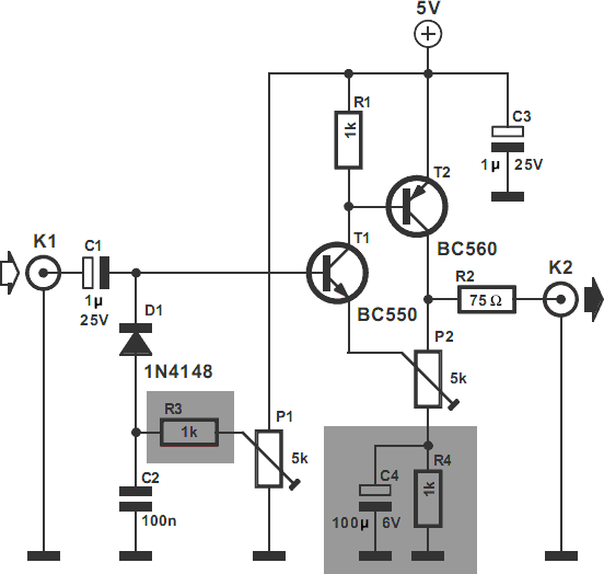
Video Amplifier Circuit
The video amplifier depicted in the diagram is a widely recognized design that is both simple and highly effective. However, the transistors are susceptible to damage if the potentiometers (black level and signal amplitude) are set to their extreme positions....
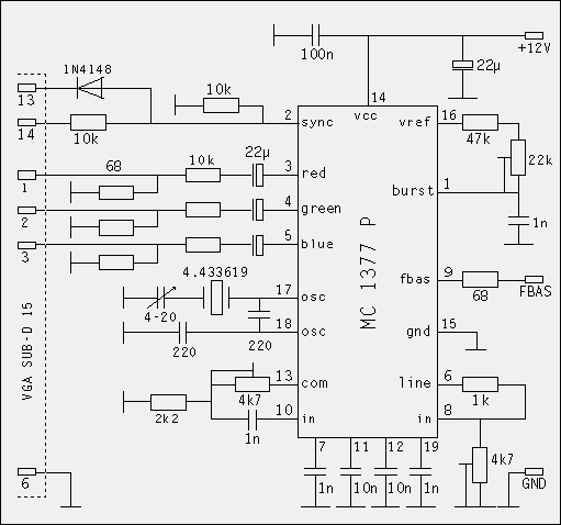
TV RGB signal output from a SVGA graphics card
The idea to produce a standard TV PAL signal using a SVGA graphics card was born a few years ago, where cheap graphics cards with TV output were still not available. To achieve a CCIR conform TV signal with 50...
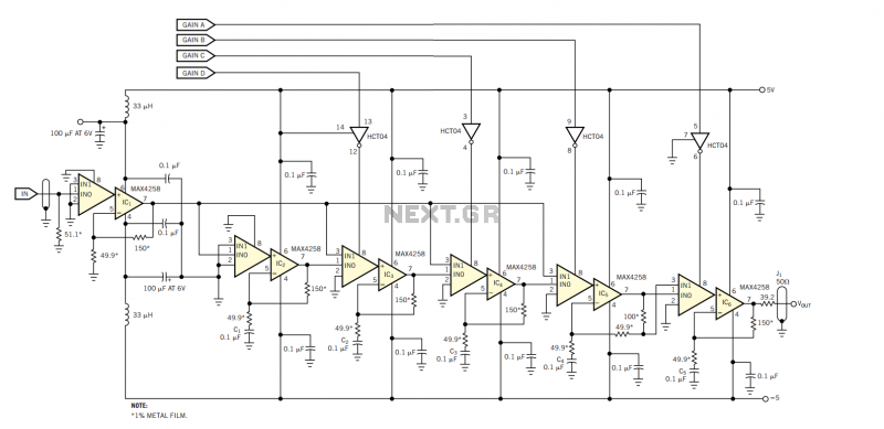
Video amplifier provides digital gain control
The amplifier in Figure 1 originally served as the photomultiplier preamplifier in a Doppler system intended for eventual operation in the Martian atmosphere. The design is based on a switchable array of six Maxim MAX4258 dual-channel video multiplexer-amplifiers, IC1 through...
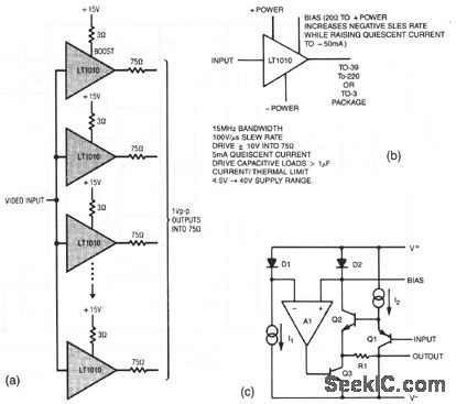
Video distribution amplifier
The resistors in the output lines are used to isolate reflections from unterminated lines. If the line characteristics are known, the resistors can be removed. To satisfy NTSC gain-phase requirements, a small-value boost resistor is employed. Figures 3-27B and 3-27C...
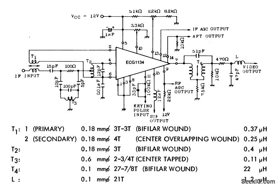
TV_video_processor
The EGG 1134 is a TV video processor that includes a picture intermediate frequency (IF) amplifier, a video detector, a video amplifier, keyed automatic gain control (AGC) with noise immunity, delayed AGC for the tuner, an automatic frequency tuning (AFT)...