


Passive EQ for STAX
#passive EQ
#STAX
#audiophile
#equalizer
#inductors
#signal processing
#high-fidelity
#audio equipment
#sound quality
#audio circuit
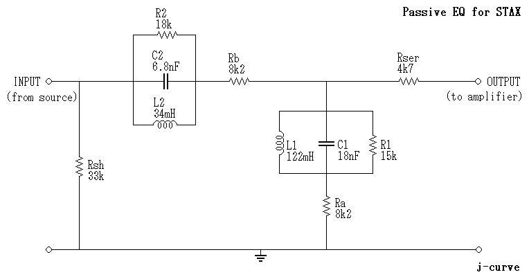
Description: Many audiophiles reject equalizers for various reasons, some of which relate not to the EQ circuit itself or its algorithm, but to the surrounding components such as operational amplifiers, transistors, and analog-to-digital (A/D) and digital-to-analog (D/A) converters. The only passive equalizer known is quite expensive and is not entirely passive, as it includes some amplification components to restore the signal to a usable level. Inductor values typically found in speaker crossovers should be researched. It is noted that these inductors are not readily available on the market. Ideally, air-cored inductors would be preferred, but some ferrite may be necessary, particularly for L1, which may require approximately 250 meters of wire, making manual winding impractical. If a reel of enameled wire with both ends exposed is available, it would be beneficial. The good news is that fencing wire is not required; even wire as fine as SWG 34 (or AWG 31, with a diameter of 0.23 mm) should suffice, as the impedances are relatively high, and a few ohms of resistance will not significantly affect performance. The inductors should be spaced apart within a metal enclosure. In the absence of an inductance meter, the tank circuits L1-C1 and L2-C2 can be tuned using an audio oscillator and a multimeter, with the inductors installed in the box during the process. A Lambda response plot produced by Moller et al. in the article "Transfer Characteristics of Headphones Measured on Human Ears," Journal of the Audio Engineering Society, v43, #4, April 1995, p215, is referenced. Toko inductors are highlighted as a valuable find, although they require a search for suitable values, as they are compact. Compromises exist, as the use of fine wire results in higher DC resistance, which should not exceed 1 ohm per mH. Other considerations include hysteresis distortion and magnetic saturation, likely due to the ferrite cores used in Toko inductors. The tuning process is intended to be a one-time adjustment to achieve the desired frequency response. This design aims to bring a Stax headset, particularly the Lambda series, closer to the diffuse field response. While the design is straightforward, it lacks adjustability. The boost and cut amounts are limited by resistors R1 and R2; replacing these with 33k-ohm linear potentiometers would allow for greater flexibility in the EQ, providing nearly 6 dB boost at 3.4 kHz and 8 dB cut at 10.5 kHz. The potentiometers can be set to zero for a flat response with no phase shift. A setting around the 12 o'clock position is anticipated to yield optimal sound quality. Dual-gang potentiometers are required for stereo applications. The Toko inductor recommendation is appreciated, as the circuit is not expected to reach magnetic saturation, and ferrite hysteresis is minimal, ensuring low distortion. Additionally, the compact and magnetically shielded nature of the inductors allows for a more compact enclosure. The "J" type with 5% tolerance is preferred. Calibration of binaural microphones is noted as a limitation. A frequency response plot may be included in the Stax handbook, but without knowledge of the measurement methodology, it may lack utility. Furthermore, a frequency response plot's significance is diminished unless compared with other headphones or a target curve.
The circuit described revolves around a passive equalizer designed for use with Stax Lambda series headphones, focusing on achieving a frequency response that approximates the diffuse field response. The design incorporates inductors and capacitors in tank circuits to create a filter network that can adjust the audio signal's spectral content. The inductors, particularly Toko inductors, are selected for their compact size and low distortion characteristics, while their placement within a metal enclosure minimizes interference and enhances performance.
The equalizer circuit's passive nature means that it does not amplify the audio signal but instead modifies it by selectively boosting or attenuating specific frequency ranges. The use of resistors R1 and R2 sets the limits for the equalization effect, while the potential replacement with dual-gang potentiometers allows for user-adjustable tuning, catering to individual listening preferences. The tuning of the inductors and capacitors is critical, as it directly influences the circuit's response characteristics. The tuning process is best performed with the components in situ, utilizing an audio oscillator to generate test tones and a multimeter to assess the response.
In summary, this passive equalizer circuit for Stax headphones is designed to provide a tailored audio experience by adjusting frequency response without introducing significant distortion or interference. The careful selection of components, particularly the inductors and capacitors, ensures that the circuit operates effectively within the desired parameters, providing audiophiles with a high-quality listening experience.Many audiophiles reject equalizers for various reasons, some of which relate not to the EQ circuit itself (or algorithm) but to the surrounding "glue" of op-amps, transistors, A/D and D/A converters etc. The only "passive" EQ I`m aware of is horribly expensive and is not actually 100% passive - it contains some amplifying glue to restore the signal to a usable level.
[Hint: Look up the values of inductors you might typically find in a speaker crossover. ] Needless to say, these suckers are not shelf items! It would be nice if they were air-cored but some ferrite may be necessary, especially for L1, where I estimate 250 metres of wire could be necessary otherwise. This is not something you want to try and wind by hand. If you can locate a reel of enamelled wire with both ends of the copper sticking out then you should be so lucky.
The good news is you don`t need fencing wire for these - even as fine as SWG 34 (or AWG 31 = 0. 23mm diameter) should be OK, as the impedances are quite high and a few ohms of resistance won`t upset things. The inductors should be placed well apart from each other in a metal box. If you don`t have an inductance meter (who does ), the tank circuits L1-C1 and L2-C2 can be tuned with an audio oscillator and a multimeter.
The inductors should be in place in the box when you do this. 2. A Lambda response plot produced by Moller et al. from the article "Transfer Characteristics of Headphones Measured on Human Ears", Journal of the Audio Engineering Society, v43, #4, April 1995, p215. Those Toko inductors are a great find! I searched a bit but didn`t turn up anything with those kinds of values, and they are so compact too(!) This involves compromises of course - they are obviously using a very fine guage of wire so the DC resistance is near the top of the tolerable range.
[More than 1 ohm per mH would be unacceptable, I think. ] The other issues are hysteresis distortion and magnetic saturation. I presume the Toko inductors are built on ferrite cores. Probably the only way to find out is to give it a go, using the closest values and playing around with a few capacitors until you get a good match. Yes, the measurements have been done previously. The tuning process is only meant to be done once, ie. set-and-forget, in order to get the desired adjustments to the frequency response. This design doesn`t let you tweak the response on-the-fly. It is supposed to bring a Stax headset (Lambda series in particular) closer to the diffuse field response.
The above design is simple but offers no adjustability. The amount of boost and cut is limited by R1 and R2, so if these were replaced with 33k-ohm linear potentiometers the EQ would be quite flexible. This would give you almost 6dB boost at 3. 4kHz and 8dB cut at 10. 5kHz. You can also wind the pots back to zero for flat response (with no phase shift either). Somewhere around 12 o`clock should sound pretty good I think. The potentiometers have to be dual-gang for stereo. Jupiter, thanks again for the Toko inductor tip. I don`t think this circuit will push them anywhere near magnetic saturation, and ferrite hysteresis is minimal so distortion should be very low.
Moreover, they are tiny and magnetically shielded, meaning they can all live happily together in a much smaller box. The "J" type with 5% tolerance will be best. No, for the simple reason that my binaural microphones aren`t calibrated. Apparently some kind of plot can be found in the handbook which comes with the Stax, but without knowing exactly how it was measured it might not help at all.
And if you did have an actual frequency response plot, what would you do with it It has little meaning unless you plot other headphones on the same graph, or a target curve such as a di
The circuit described revolves around a passive equalizer designed for use with Stax Lambda series headphones, focusing on achieving a frequency response that approximates the diffuse field response. The design incorporates inductors and capacitors in tank circuits to create a filter network that can adjust the audio signal's spectral content. The inductors, particularly Toko inductors, are selected for their compact size and low distortion characteristics, while their placement within a metal enclosure minimizes interference and enhances performance.
The equalizer circuit's passive nature means that it does not amplify the audio signal but instead modifies it by selectively boosting or attenuating specific frequency ranges. The use of resistors R1 and R2 sets the limits for the equalization effect, while the potential replacement with dual-gang potentiometers allows for user-adjustable tuning, catering to individual listening preferences. The tuning of the inductors and capacitors is critical, as it directly influences the circuit's response characteristics. The tuning process is best performed with the components in situ, utilizing an audio oscillator to generate test tones and a multimeter to assess the response.
In summary, this passive equalizer circuit for Stax headphones is designed to provide a tailored audio experience by adjusting frequency response without introducing significant distortion or interference. The careful selection of components, particularly the inductors and capacitors, ensures that the circuit operates effectively within the desired parameters, providing audiophiles with a high-quality listening experience.Many audiophiles reject equalizers for various reasons, some of which relate not to the EQ circuit itself (or algorithm) but to the surrounding "glue" of op-amps, transistors, A/D and D/A converters etc. The only "passive" EQ I`m aware of is horribly expensive and is not actually 100% passive - it contains some amplifying glue to restore the signal to a usable level.
[Hint: Look up the values of inductors you might typically find in a speaker crossover. ] Needless to say, these suckers are not shelf items! It would be nice if they were air-cored but some ferrite may be necessary, especially for L1, where I estimate 250 metres of wire could be necessary otherwise. This is not something you want to try and wind by hand. If you can locate a reel of enamelled wire with both ends of the copper sticking out then you should be so lucky.
The good news is you don`t need fencing wire for these - even as fine as SWG 34 (or AWG 31 = 0. 23mm diameter) should be OK, as the impedances are quite high and a few ohms of resistance won`t upset things. The inductors should be placed well apart from each other in a metal box. If you don`t have an inductance meter (who does ), the tank circuits L1-C1 and L2-C2 can be tuned with an audio oscillator and a multimeter.
The inductors should be in place in the box when you do this. 2. A Lambda response plot produced by Moller et al. from the article "Transfer Characteristics of Headphones Measured on Human Ears", Journal of the Audio Engineering Society, v43, #4, April 1995, p215. Those Toko inductors are a great find! I searched a bit but didn`t turn up anything with those kinds of values, and they are so compact too(!) This involves compromises of course - they are obviously using a very fine guage of wire so the DC resistance is near the top of the tolerable range.
[More than 1 ohm per mH would be unacceptable, I think. ] The other issues are hysteresis distortion and magnetic saturation. I presume the Toko inductors are built on ferrite cores. Probably the only way to find out is to give it a go, using the closest values and playing around with a few capacitors until you get a good match. Yes, the measurements have been done previously. The tuning process is only meant to be done once, ie. set-and-forget, in order to get the desired adjustments to the frequency response. This design doesn`t let you tweak the response on-the-fly. It is supposed to bring a Stax headset (Lambda series in particular) closer to the diffuse field response.
The above design is simple but offers no adjustability. The amount of boost and cut is limited by R1 and R2, so if these were replaced with 33k-ohm linear potentiometers the EQ would be quite flexible. This would give you almost 6dB boost at 3. 4kHz and 8dB cut at 10. 5kHz. You can also wind the pots back to zero for flat response (with no phase shift either). Somewhere around 12 o`clock should sound pretty good I think. The potentiometers have to be dual-gang for stereo. Jupiter, thanks again for the Toko inductor tip. I don`t think this circuit will push them anywhere near magnetic saturation, and ferrite hysteresis is minimal so distortion should be very low.
Moreover, they are tiny and magnetically shielded, meaning they can all live happily together in a much smaller box. The "J" type with 5% tolerance will be best. No, for the simple reason that my binaural microphones aren`t calibrated. Apparently some kind of plot can be found in the handbook which comes with the Stax, but without knowing exactly how it was measured it might not help at all.
And if you did have an actual frequency response plot, what would you do with it It has little meaning unless you plot other headphones on the same graph, or a target curve such as a di
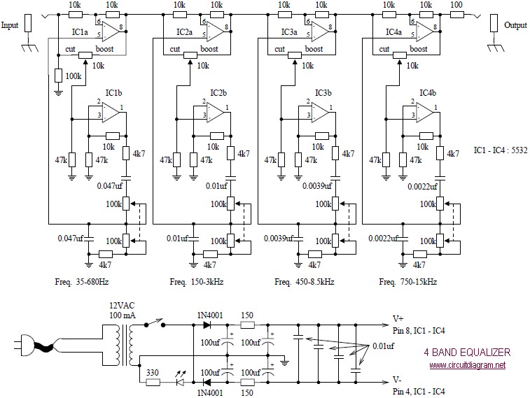
4 Band Equalizer schematic diagram
The following diagram illustrates a four-band blaster circuit. This blaster is utilized to enhance sound fidelity, emphasize specific instruments, eliminate unwanted noise, or create entirely new and distinct timbres.
The four-band blaster circuit is designed to manipulate audio signals across four...
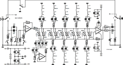
10 band equalizer
The equalizer described is designed for hi-fi installations, public address systems, mixers, and electronic musical instruments. Relay contacts at the inputs and outputs, in conjunction with switch S2, allow for the selection of the desired channel. The input can be...
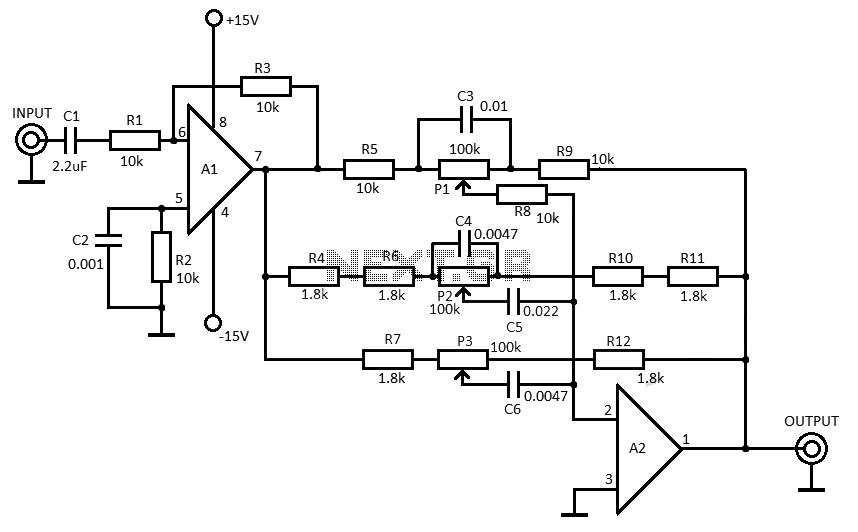
3 band equalizer circuit
This 3-band equalizer circuit is an active filter network designed to adjust bass, midrange, and treble audio frequencies. It utilizes the LM833 operational amplifier from National Semiconductors, which is known for its very low noise figure and wide frequency response.
The...
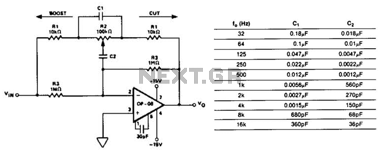
Octave Equalizer Circuit
This circuit represents a section of an octave equalizer utilized in audio systems. The table outlines the values of C1 and C2 required to achieve specific center frequencies. This circuit can provide a boost or cut of 12 dB, which...
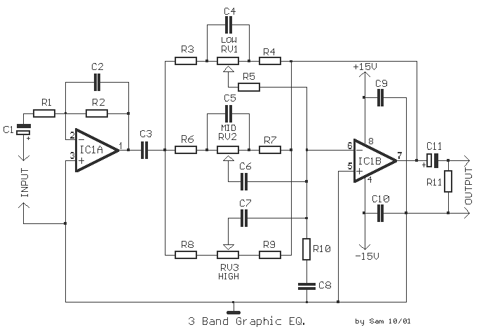
3 Band Equalizer
The description refers to a classic three-way tone regulation circuit, which allows for the adjustment of low, mid, and high frequencies of an acoustic signal. The boost or cut can be adjusted within a range of ± 18 dB/oct. The...
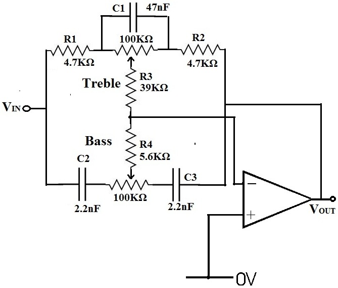
Audio Equalizer
An equalizer is a device that allows for the adjustment of the gains of individual frequencies. For instance, to reduce bass, one would navigate to the frequency range around 500Hz and decrease the volume. Conversely, to enhance treble, one would...
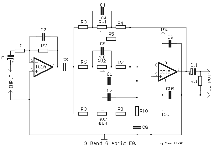
3 band equalizer
A classic three-way tone control circuit that allows for the regulation of low, mid, and high frequencies of an acoustic signal. The boost/cut can be adjusted within a range of ± 18 dB/oct. The circuit operates on a supply voltage...
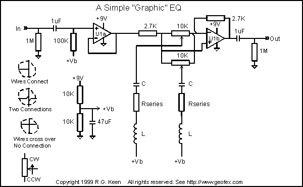
Simple Easy Parametric and Graphic EQs Plus Peaks and Notches
The sound of a wah pedal is characterized by a resonant peak in the signal that can be adjusted. In contrast, a notch represents a sudden decrease in level at a specific frequency, which can be advantageous for achieving particular...

Ten-Band Equalizer
The equalizer discussed in this article is appropriate for use with high-fidelity installations, public address systems, mixers, and electronic musical instruments.
The equalizer is an essential audio processing device that allows for the adjustment of specific frequency bands within an audio...