


Car Horn
#car horn
#sound generator
#automotive modification
#audio circuit
#vehicle electronics
#tone control
#potentiometer
#capacitor network
#resistor network
#car accessory
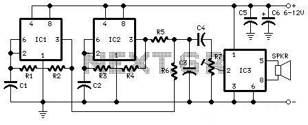
Description: The following diagram is the schematic diagram for a car horn circuit that can be utilized for car modifications. Components List: R1 = 68K, R2 = 2K2, R3 = 56K, R4 = 3K3, R5, R6 = 4K7, R7 = 10K Pot/trimpot, C1, C2 = 22nF, C3, C5 = 100nF, C4 = 1nF, C6 = 22nF.
The car horn circuit schematic serves as a guide for automotive enthusiasts looking to modify or enhance their vehicle's horn system. The circuit consists of various resistors, capacitors, and a potentiometer, each playing a critical role in the operation of the horn.
The resistors, designated as R1, R2, R3, R4, R5, R6, and R7, are used to set the biasing conditions and control the current flow within the circuit. Resistor R1, with a value of 68K, helps in limiting the current to protect sensitive components. R2 at 2K2 and R3 at 56K are used for voltage division and signal conditioning, while R4 at 3K3 and the pair of R5 and R6 at 4K7 each help in controlling the overall gain of the circuit. R7, a 10K potentiometer, provides the ability to adjust the output level, allowing for customization of the horn's sound intensity.
The capacitors, labeled C1 through C6, are crucial for filtering and smoothing the signal. C1 and C2, both rated at 22nF, are used for high-frequency noise filtering, ensuring that the horn operates smoothly without unwanted interference. Capacitors C3 and C5, rated at 100nF, serve a similar purpose but are tailored for different sections of the circuit to stabilize voltage levels. C4, with a value of 1nF, is likely used for decoupling purposes, while C6, also at 22nF, may serve as a coupling capacitor to block DC voltage while allowing AC signals to pass through.
This schematic can be implemented as part of a broader modification project, enhancing the auditory signaling capabilities of a vehicle. Proper assembly and adherence to the specified component values are essential for optimal performance. Additionally, careful attention should be paid to the power supply requirements and the integration of this circuit with existing automotive systems to ensure reliable operation.The following diagram is the schematic diagram fo Car Horn, you may try this circuit for your car modification Components List: R1 = 68K R2 = 2K2 R3 = 56K R4 = 3K3 R5,R6 = 4K7 R7 = 10K Pot/trimpot C1,C2 = 22nF C3,C5 = 100nF C4 = 1nF C6 = 22..
The car horn circuit schematic serves as a guide for automotive enthusiasts looking to modify or enhance their vehicle's horn system. The circuit consists of various resistors, capacitors, and a potentiometer, each playing a critical role in the operation of the horn.
The resistors, designated as R1, R2, R3, R4, R5, R6, and R7, are used to set the biasing conditions and control the current flow within the circuit. Resistor R1, with a value of 68K, helps in limiting the current to protect sensitive components. R2 at 2K2 and R3 at 56K are used for voltage division and signal conditioning, while R4 at 3K3 and the pair of R5 and R6 at 4K7 each help in controlling the overall gain of the circuit. R7, a 10K potentiometer, provides the ability to adjust the output level, allowing for customization of the horn's sound intensity.
The capacitors, labeled C1 through C6, are crucial for filtering and smoothing the signal. C1 and C2, both rated at 22nF, are used for high-frequency noise filtering, ensuring that the horn operates smoothly without unwanted interference. Capacitors C3 and C5, rated at 100nF, serve a similar purpose but are tailored for different sections of the circuit to stabilize voltage levels. C4, with a value of 1nF, is likely used for decoupling purposes, while C6, also at 22nF, may serve as a coupling capacitor to block DC voltage while allowing AC signals to pass through.
This schematic can be implemented as part of a broader modification project, enhancing the auditory signaling capabilities of a vehicle. Proper assembly and adherence to the specified component values are essential for optimal performance. Additionally, careful attention should be paid to the power supply requirements and the integration of this circuit with existing automotive systems to ensure reliable operation.The following diagram is the schematic diagram fo Car Horn, you may try this circuit for your car modification Components List: R1 = 68K R2 = 2K2 R3 = 56K R4 = 3K3 R5,R6 = 4K7 R7 = 10K Pot/trimpot C1,C2 = 22nF C3,C5 = 100nF C4 = 1nF C6 = 22..
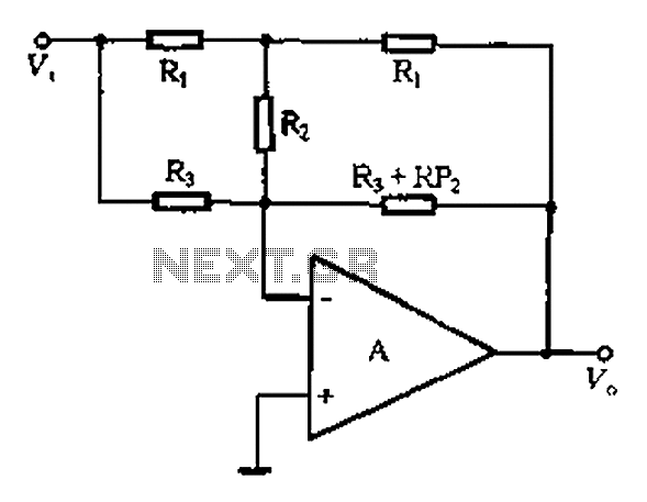
Integrated operational amplifier tone control circuit of a simplified equivalent circuit a
At high frequencies, the capacitor Cz can be considered a short circuit (i.e., the resistance of the RPi is negligible). This is illustrated in Figure 4-6 (a) of the apparatus, which corresponds to the equivalent circuit shown in Figure 4-6...
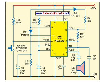
Car Reversing Horn With Flasher
This circuit activates the car horn when the vehicle is in reverse gear. It utilizes a dual timer NE556 to generate the necessary signals.
The described circuit employs a dual timer IC, specifically the NE556, which is a versatile component commonly...
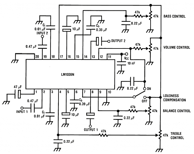
Bass-treble tone control circuits
Low distortion bass and treble control for an amplifier. Circuit diagram. Electronics project.
The low distortion bass and treble control circuit is designed to enhance the audio quality of an amplifier by allowing precise adjustments to the low and high-frequency response....
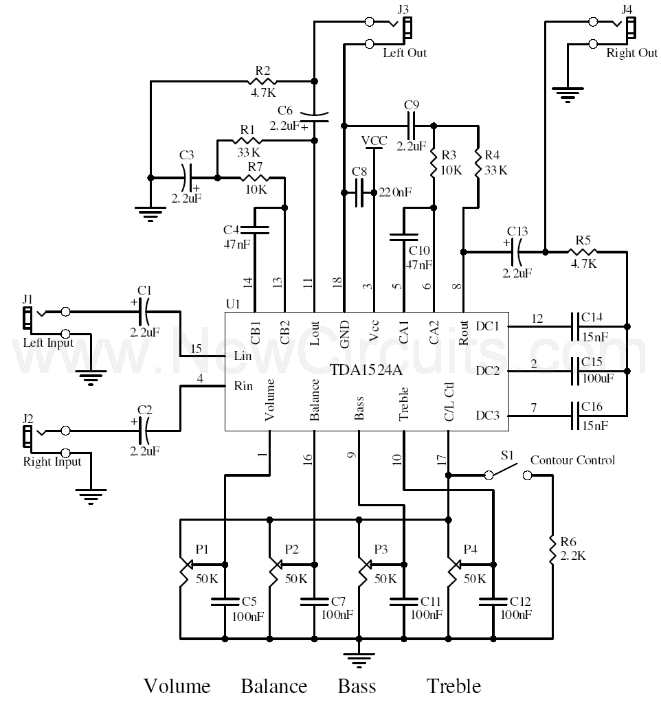
Stereo Tone Control
This simple tone control can be used in many audio applications. It can be added to amplifiers, used as a standalone control module, or even built into new and exciting instruments. Its single integrated circuit (IC) construction makes it a...
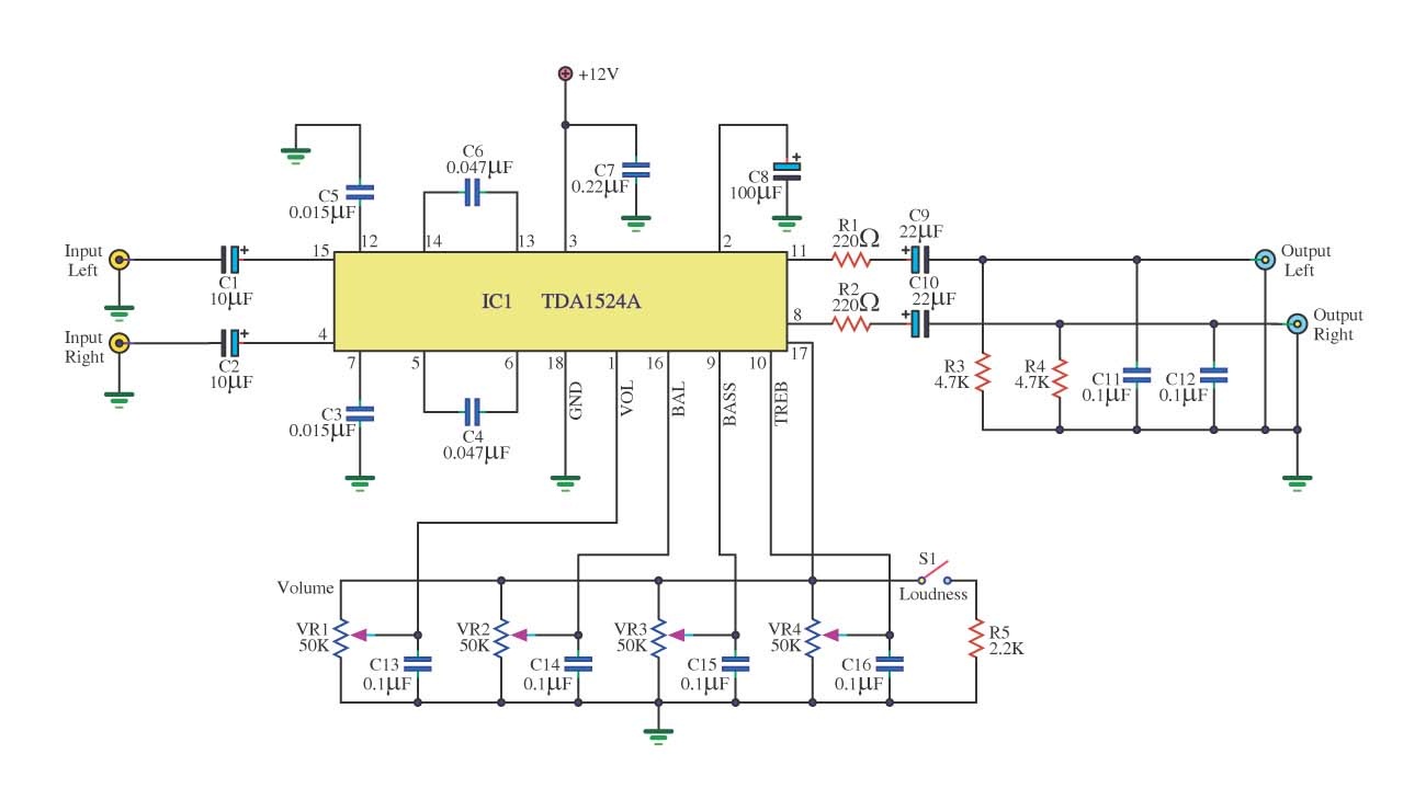
tone control circuit using tda1524a
This is a simple tone control circuit using the TDA1524A, which is a key component in this IC chip diagram from Philips. The circuit allows for tone control adjustments such as bass, treble, and balance, enabling users to fine-tune the...
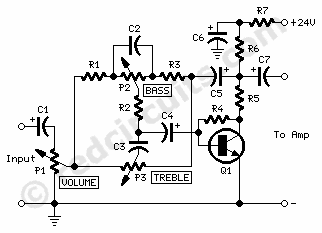
Tone ControlCircuit
P1 47K logarithmic potentiometer; P2, P3 47K linear potentiometers; R1, R3, R5 4.7K 1/4W resistors; R2 22K 1/4W resistor; R4 1M 1/4W resistor; R6 1.8K 1/4W resistor; R7 560Ω 1/4W resistor; C1, C4, C5, C7 10 µF 63V electrolytic capacitors;...
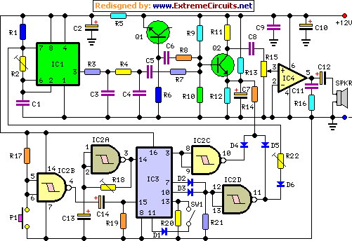
Cuckoo Sound Generator Circuit Schematic
This circuit generates a two-tone effect similar to the cuckoo song. It can be used for doorbells or other applications due to a built-in audio amplifier and loudspeaker. As a sound effect generator, it can be connected to external amplifiers,...
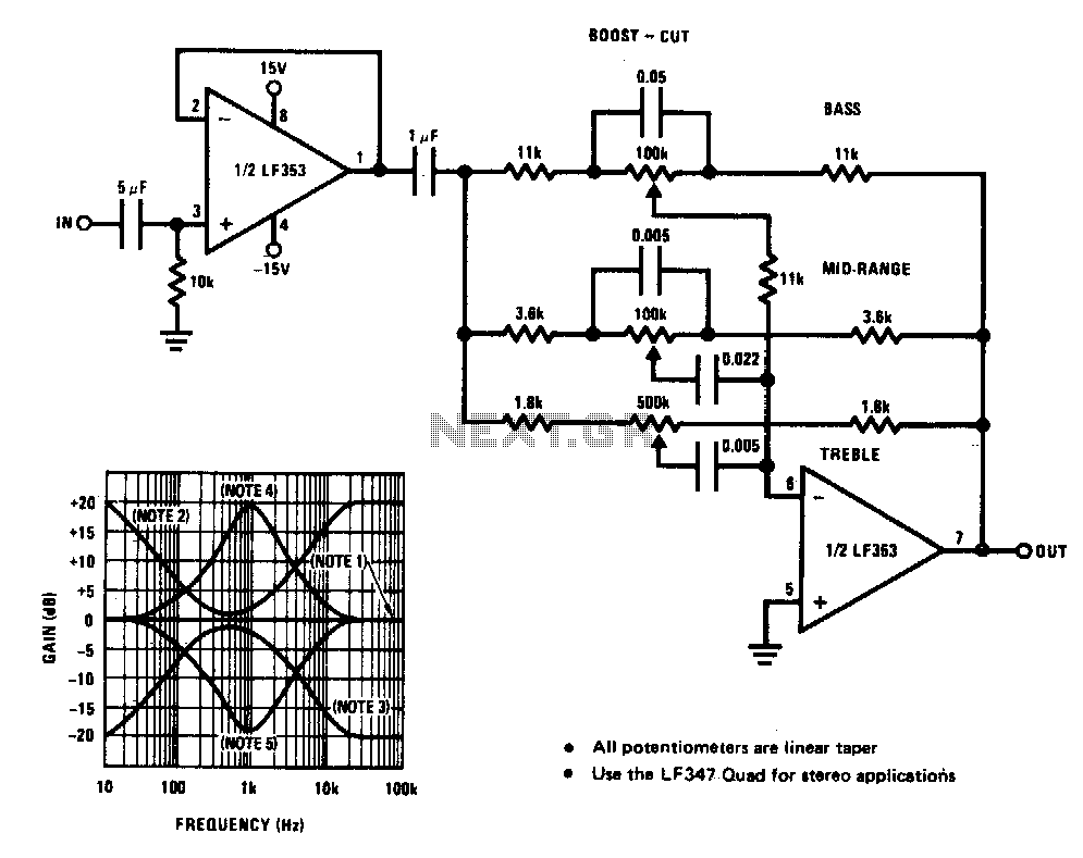
Tone control circuit
A simple single-transistor circuit provides an approximate 15 dB boost at 100 Hz and a 15 dB cut at 15 kHz. A low-noise audio transistor is utilized, and the output can be directly connected to any existing amplifier volume control...
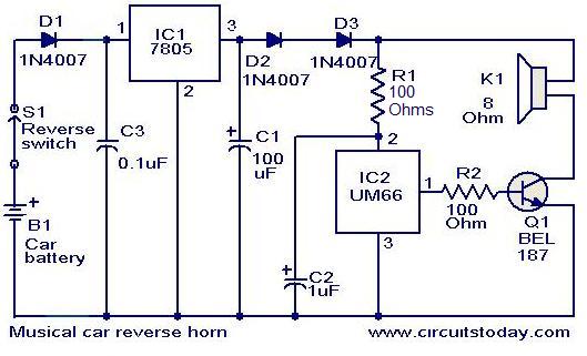
Musical car reverse horn circuit
This circuit is designed to produce a musical horn whenever a car is in reverse gear. It utilizes two integrated circuits (ICs) for its operation: a voltage regulator (7805, referred to as IC1) and a musical tone generator (UM66, referred...